Mounting positions of the different versions, Mounting positions 8 – AUMA Part-turn gearboxes GS 50.3 - 250.3, primary reduction gearings VZ 2.3 - 4.3_GZ 160.3 - 250.3 User Manual
Page 8
5.
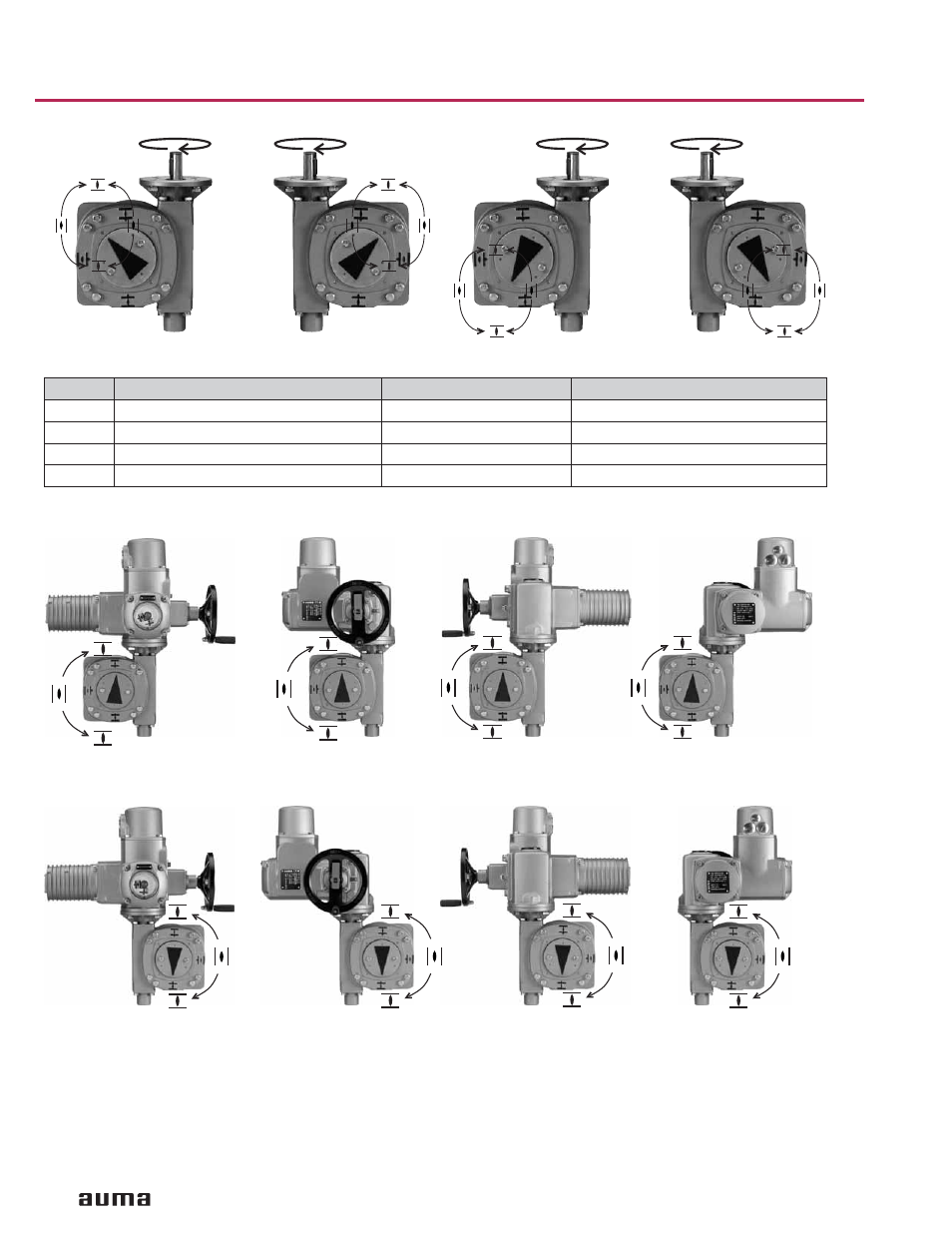
Mounting positions of the different versions
8
Worm gearboxes GS 50.3 – GS 250.3
Operation instructions
C
RR
RL
B
RR
RL
D
RR
RL
B
C
LL
LR
D
LL
LR
A
LL
LR
A
RR
RL
GS versions LL / LR
Description of the 4 versions (viewed at the pointer cover):
LL
LR
RR
LL
RL
LR
Mounting positions of AUMA multi-turn actuator with AUMA worm gearbox (please indicate when ordering)
GS versions RR / RL
Mounting positions can easily be changed at a later date.
Limitation: For SA/SAR 14.1/14.5 with GS 125.3, mounting position “C” in version RR/RL and “A” in version LL/LR is
only possible for a handwheel diameter up to 12.4 ”.
Up to size GS 125.3, the actuator-gearbox combination is delivered in the ordered mounting position. For packing
reasons, actuator and gearbox is delivered separately from size GS 160.3.
Code
Direction of rotation at input shaft
Position of worm shaft
Direction of rotation at output drive
RR
clockwise
Right side
clockwise
LL
clockwise
Left side
counterclockwise
RL
clockwise
Right side
counterclockwise
LR
clockwise
Left side
clockwise