Setting the end stops for manual operation, 1 worm gearboxes on butterfly valves, Manual operation 12 – AUMA Part-turn gearboxes GS 50.3 - 250.3, primary reduction gearings VZ 2.3 - 4.3_GZ 160.3 - 250.3 User Manual
Page 12: For manual operation 12, Worm gearboxes on butterfly valves
8.
Setting the end stops for manual operation
If worm gearboxes GS are supplied on a valve the end stops are
already set by the valve manufacturer.
8.1
Worm gearboxes on butterfly valves
Setting end position CLOSED
.
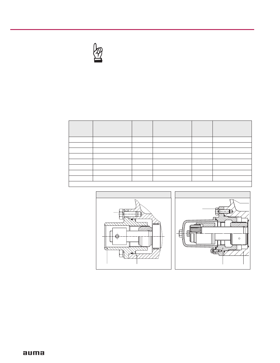
Remove all bolts (03) at limit stop housing (figures D, E).
.
Turn valve manually to end position CLOSED.
.
In case limit stop housing (10) has not yet rotated, turn it clockwise up to the
stop.
.
If the holes of limit stop housing (10) do not align with the threads of the housing
(1), take off the limit stop housing (10) and replace it in the required position.
.
Fasten bolts (03) with lock washers (04).
.
Fasten bolts crosswise with a torque according to table 3.
.
If the position of the pointer cover does not correspond to the symbol CLOSED,
slightly loosen the screws of the pointer cover. Turn the pointer cover to the
CLOSED symbol and fasten the screws again.
Setting end position OPEN
The end stop need not be set since the required swing angle has been set in the
factory.
If the swing angle does not match, refer to section 10.
12
Worm gearboxes GS 50.3 – GS 250.3
Operation instructions
Gearbox
End stops fas-
tened with
bolts (03)
Material
Protective cap
fastened with
bolts (054)
Material
Fastening torque
T
A
[Nm]
GS 50.3
M 8
A2-80
24
GS 63.3
M 8
A2-80
24
GS 80.3
M 8
A2-80
24
GS 100.3
M 12
A2-80
82
GS 125.3
M 12
A2-80
82
GS 160.3
M 10
A2-80
M 6
A2-80
48
GS 200.3
M 12
A2-80
M 6
A2-80
82
GS 250.3
M 16
A2-80
M 6
A2-80
200
Conversion factor: 1 Nm corresponds to 0.74 ft lbs.
Table 3
03/04
10
1
Figure D: End stop up to GS 125.3
03/04
10
1
Figure E: End stop from GS 160.3