Sr560 low-noise preamplifier, Preamplifier block diagram – Atec Stanford-SR560 User Manual
Page 2
phone: (408)744-9040
www.thinkSRS.com
Stanford Research Systems
SR560 Low-Noise Preamplifier
provide up to 200 mA of ±12 VDC referenced to the amplifier
ground. The outputs provide clean DC power for use as a
bias source.
Gain
Gain is selectable from 1 to 50,000 in a 1-2-5 sequence.
An adjustable gain feature lets you specify the gain as a
percentage of any of the fixed gain settings with 0.5 %
resolution. Gain can be selectively allocated before the filters
to optimize noise performance, or after the filters to reduce
susceptibility to overloads.
Filters
The SR560 contains two first-order RC filters whose cutoff
frequency and type (HPF or LPF) can be configured from the
front panel. Together, the filters can be configured as a 6 or
12 dB/oct rolloff low-pass or high-pass filter, or as a 6 dB/oct
rolloff band-pass filter. A filter reset button is included to shorten
the overload recovery time of the instrument when long filter
time constants are being used. Filter cutoff frequencies can be set
in a 1-3-10 sequence from 0.03 Hz to 1 MHz.
Battery Operation
Three rechargeable lead-acid batteries provide up to 15 hours
of battery powered operation. An internal battery charger
automatically charges the batteries when the unit is connected
to the line. The charger senses the battery state and adjusts
the charging rate accordingly. Two rear-panel LEDs indicate
the charge state of the batteries. When the batteries become
discharged, they are automatically disconnected from the
amplifier circuit to avoid battery damage.
No Digital Noise
The microprocessor that runs the SR560 is “asleep” except
during the brief interval it takes to change the instrument’s
setup. This ensures that no digital noise will contaminate low-
level analog signals.
RS-232 Interface
The RS-232 interface allows listen-only communication with
the SR560 at 9600 baud. Up to four SR560s can be controlled
from a single computer, with each SR560 being assigned a
unique address. A “Listen” command specifies which SR560
will respond to commands on the RS-232 line. All functions
of the instrument (except power on) can be set via the RS-232
interface. The RS-232 interface is opto-isolated from the
amplifier circuitry to provide maximum noise immunity.
10 Hz
1 Hz
100 Hz
1 kHz
10 kHz
100 kHz
1 MHz
10 MHz
0 dB
10 dB
20 dB
30 dB
40 dB
50 dB
10 mV
100 mV
1 V
3 V
A =1000
BPF 1 kHz - 10 kHz
v
High Dynamic Reserve
6 dB/octave
20 dB/decade
(due to LPF)
Low Noise
6 dB/octave
20 dB/decade
(due to HPF)
Frequency
Dynamic Reser
ve
Dynamic reserve vs. frequency
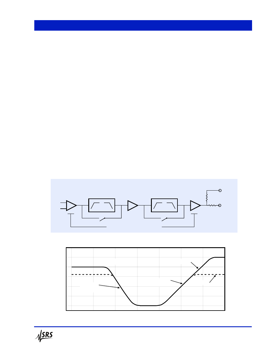
Front End
Filter 1
Outputs
Signal
Amplifier
Filter 2
Output
Amplifier
600
Ω
50
Ω
A
B
DYNAMIC RESERVE ALLOCATION
PREAMPLIFIER BLOCK DIAGRAM