100 mhz band differential probe, Specifications – Atec Yokogawa-700924 User Manual
Page 2
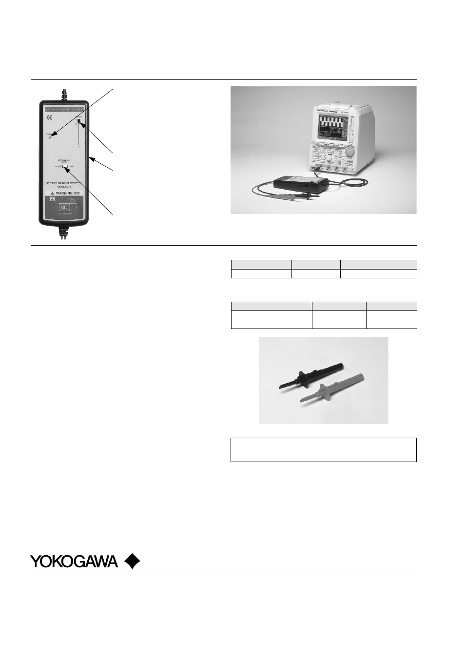
100 MHz band differential probe
Subject to change without notice.
[Ed : 01/b] Copyright ©1999
Printed in Japan, 907(YG)
YOKOGAWA ELECTRIC CORPORATION
Measurement Sales Dept./Phone: 81-422-52-6614, Fax: 81-422-52-6624
Recorders · DAC Sales Dept./Phone : 81-422-52-6765, Fax : 81-422-52-6793
YOKOGAWA CORPORATION OF AMERICA
Phone: 770-253-7000, Fax: 770-251-2088
YOKOGAWA EUROPE B.V.
Phone: 31-33-4-641611, Fax: 31-33-4-631202
YOKOGAWA ENGINEERING ASIA PTE. LTD Phone: 65-783-9537, Fax: 65-786-6650
MS-06E
700924
Example of probe connection with DL1540CL digital oscilloscope
Two or more differential probes can be connected to measure signals with different ground
levels on each channel.
●
Overrange (outside-range) indicator
This light turns on when the permitted
differential voltage is exceeded. During
DC measurements, it turns on as an
alert at voltages of 350 V and higher
with a 1/100 range setting, and at
voltages of 1400 V and higher with a
1/1000 range setting.
●
Power switch
●
AC/DC adapter connector
(on side of probe)
This DC adapter powers the probe. The
probe can also be powered by four dry
cells without using an AC/DC adapter.
●
1/100-1/1000 selector switch
This switch is used to select the input
voltage attenuation ratio.
■
Specifications
Input type:
Balanced differential input
Frequency band:
DC up to 100 MHz (-3 dB)
Input attenuation ratio:
Switched between 1/100 and 1/1000
Input impedance:
Approximately 4 M
Ω
, approximately 10
pF parallel
Gain accuracy:
±
2% (common mode voltage
Ϲ
400 V)
±
3% (common mode voltage
Ϲ
1000 V)
Maximum allowed differential voltage:
±
350 V (DC + ACpeak) or 250 Vrms (1/
100 range)
±
1400 V (DC + ACpeak) or 1000 Vrms
(1/1000 range)
Maximum common mode input voltage:
±
1400 V (DC + ACpeak) or 1000 Vrms
(both 1/100 and 1/1000 ranges)
Maximum input voltage:
±
1400 V (DC + ACpeak) or 1000 Vrms
(1/1000 range)
Common Mode Rejection Ratio (CMRR):
-80 dB (60 Hz), -50 dB (1 MHz)
Output voltage:
±
3.5 V
Output impedance:
Used with 1 M
Ω
input impedance
Power supplies:
Dry cells, four R6P (SUM-3); when using
the AC/DC adapter, use an output voltage
of 6 V/200 mA or greater/center plus
Dry cell life:
Approximately 2 hours under continuous
use
External dimensions (approximate):
207 mm
✕
83 mm
✕
38 mm*
1
Total length:
Approximately 1.5 meters
Weight:
Approximately 800 grams (excluding dry
cells)
Approved standards:
EMC:
EN55011: 1991 + A1: 1997 + A2: 1996
EN50082-1: 1992
Safety:
EN61010-1: 1993 + A2: 1995
EN61010-2-031: 1994
*1: 38 mm is listed as the maximum value.
Note: Dry cells and AC/DC adapter not included.
Model name
Code
Description
Differential probe
700924
DC to 100 MHz band
■
Model and Codes
Each 700924 differential probe comes standard with red and black pincher tips (one each).
Item
Part No.
Order Q'ty
Red pincher chips
B9852MC
3
Black pincher chips
B9852MB
3
■
Spares
Use this product in combination with 701856 (high-speed module) when using it with
DL708E or DL716. See the DL Series accessory catalog for information on selecting a
conversion adapter and other components. Bulletin 7009-63E