Atec Thermonics-T2420 User Manual
T-2420 specifications, General description, Physical description
T-2420 SPECIFICATIONS
3350 Scott Boulevard, Building No. 32
Santa Clara, California 95054-3118
Phone: 408.496.6838
Fax: 408.496.6918
E-Mail: [email protected]
URL: http://www.thermonics.com
Specifications subject to change without notice.
©
6/96 Thermonics
Printed in U.S.A.
GENERAL DESCRIPTION
Method of Cooling: Forced air with single-stage mechanical refrig-
eration and multistage self-cooling heat exchanger.
Method of Heating: Forced air with in-line air heaters.
Operator Interface: Twenty character alphanumeric display and
keypad; menu-driven software with self-diagnostics.
Controls: Microprocessor control of all critical functions.
PHYSICAL DESCRIPTION
Model #
Height
Width
Depth
Weight
(in/cm)
(in/cm)
(in/cm)
(lbs/kgm)
T-2420
40/102
24/61
21/53
290/132
T-2420 with
TF-1C5 or TF-IC7
48/123
24/61
49/124
355/161
POWER REQUIREMENTS
Model #
Volts (AC)
Hertz
Phases
Amps
T-2420
208
–
23050
/60 1
φ
20
TEMPERATURE PERFORMANCE
Model #
Range
Accuracy
Stability
Displayed
Transition
(°C)*
(°C)
(°C)
Resolution(°C)
Time (sec)
†
T-2420 with
T-BOH
-75
–200
±1.0
±0.3
0.1
150
T-2420SX with
T-BOH
-85
–225
±1.0
±0.3
0.1
120
T-2420 with
TF-IC5
-75
–205
±1.0
±0.3
0.1
90
T-2420 with
TF-IC7
-75
–225
±1.0
±0.3
0.1
5
T-2420SX with
TF-IC7
-85
–225
±1.0
±0.3
0.1
4
FEATURES
Calibration: Automatic or manual. Up to 10 different applications may be cali-
brated independently and stored in non-volatile memory.
Temperature Sensor: Device under test (DUT), K-type thermocouple. Optional
T-type thermocouple. 1000 ohm RTD for auto calibration.
Controller: Microprocessor-based PID (Proportional, Integral, Differential) with
user control of DUT mass constant.
Fail Safes: Snap disc thermostats, air flow sensors and thermocouples. Over tem-
perature limit of 235
°
C.
Air Dryer: Dries air to -70
°
C dew point.
Air Flow: 200 to 960 SCFH (1.6 to 7.6 liters/sec)
*
Cold specifications are for room ambient temp. of 75 F, or lower, with 60 Hz power.
†
Transition time is from +125 C to -55 C or -55 C to +125 C; air temperature measured at air
output nozzle. Measured in temperature cycle mode after system stabilization with a 10 second
soak time, or less, at each temperature. Room ambient temperature to be below 75
°
F
.
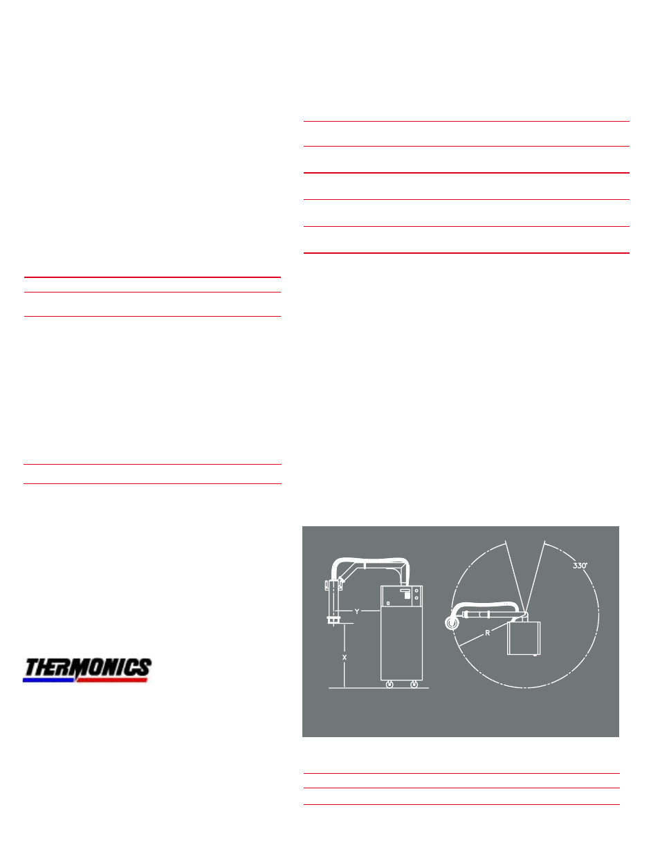
X
Y
R
(in/cm)
(in/cm)
(in/cm)
ARM
MAX
MIN
MAX
MIN
MAX
MIN
TF-IC5
57/145
24/61
30/76
18/46
54/137
38/96
TF-IC7
57/145
24/61
30/76
18/46
54/137
38/96
ENVIRONMENT
Ambient temperature range:
Operating:
15
°
C to 28
°
C
Non-Operating:
-40
°
C to +85
°
C
Relative Humidity: 20 to 65%
AIR INPUT REQUIREMENTS
Pressure:80-110 PSIG (5.7 to 7.8 Kg/cm
2
)
Flow Rate: 10-16 SCFM (4.7-7.6 liters/sec)
Dew Point: Less than 10C at 80
PSIG (5.7Kg/cm2)
Quality: Clean, dry air, free of oil, moisture and particles.
Optional transformers are available for input voltage ranges of 195-
210 VAC or 220-245 VAC.
FRONT VIEW
TOP VIEW
A Test Enterprises Company