Atec Zimmer-Electronic-Systems-LMG500 User Manual
Page 4
2
3
f=var
1
f=50Hz
L
N
V
U
4
A
I
4
A
V
U
1
V
U
2
V
U
3
A
I
1
A
I
2
I
3
Motor
1
3
4
5
6
DC
3
f=50Hz
A
I
3
V
U
1
A
I
2
A
I
1
V
U
2
V
U
3
DC
3
f=50Hz
A
I
8
V
U
6
A
I
7
A
I
6
V
U
7
V
U
8
A
I
4
A
I
5
V
U
4
V
U
5
L
2
L
3
L
1
N
2
3
1
n
I
4
-I
5
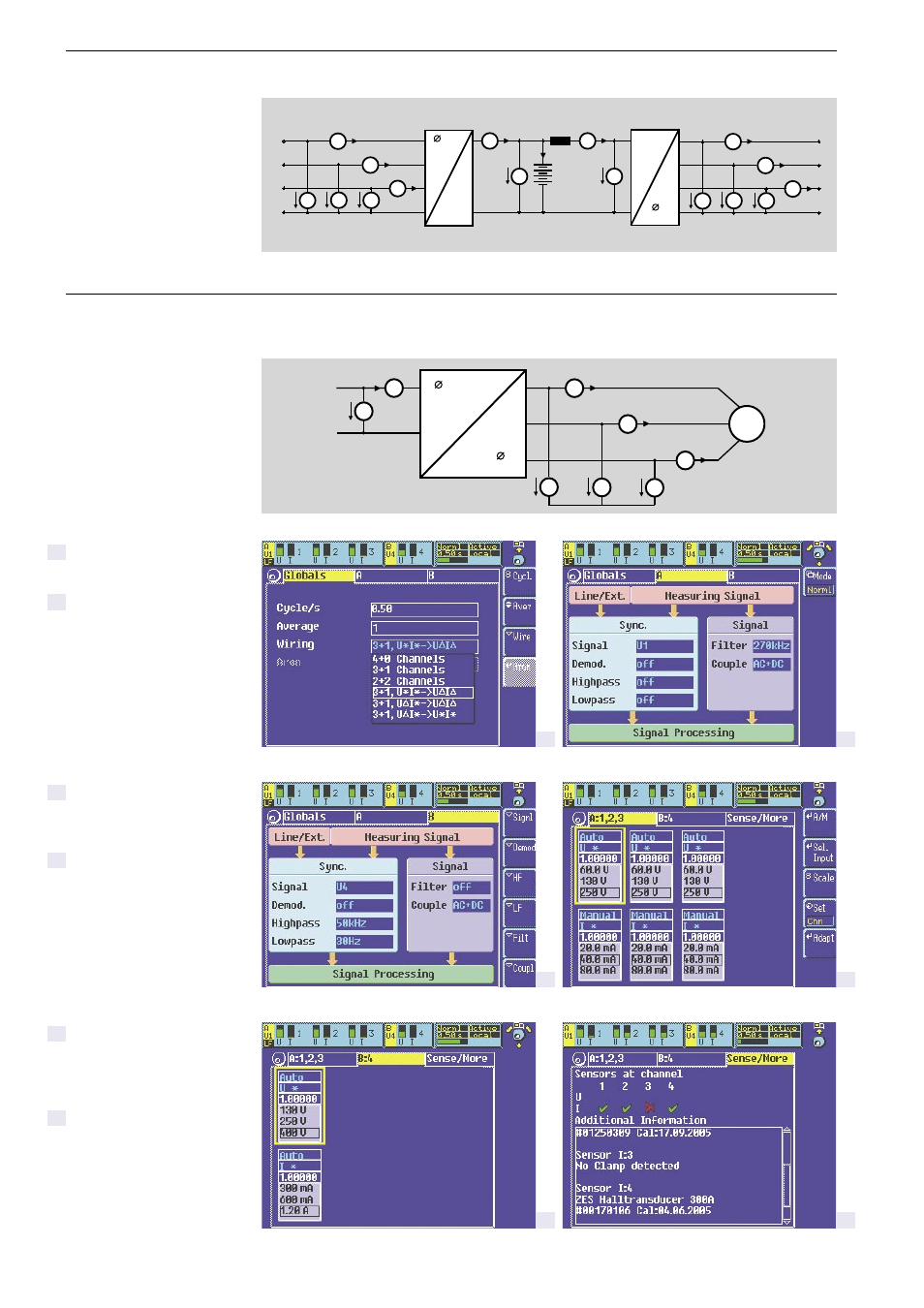
Measurements with up to
8 power channels
The following block diagram
applies wiring A:1+2+3 B:4 and
is typical for a low power speed
8 channel measuring at uninterruptible power supply with intermediate DC link
variable drive. This example is
used to explain the settings
and displays of the LMG500.
Arrangement of measurement example described with the screenshots below
Setting of global parameters,
e.g. wiring
Conditioning of measuring
signal, setting of sychronisa-
tion source for group A
Conditioning of measuring
signal, setting of sychronisa-
tion source for group B
Measuring ranges, “autorange”
or “manual”, setting of scaling
factors for current and voltage
of group A
Measuring ranges, “autorange”
or “manual”, setting of scaling
factors for current and voltage
of group B
Recognizing, displaying and
activation of connected
external current sensor devices
1
3
4
5
6
2
Example for a measuring with 8 power channels: Uninterruptible power supply with intermediate
direct current link, determination of efficiencies at different states.
Efficiency at
asychronous in- and output
(measurement example)
The screenshots were made with
the free software BMP2PC from
ZES ZIMMER.