Optional 16-character front panel display, Optional 1 pp2s output (even-second ooutput), Antenna and cabling information – Atec HP-Symmetricom-58503B User Manual
Page 3: 10 mhz output specifications (with sa on)
3
FIG.3
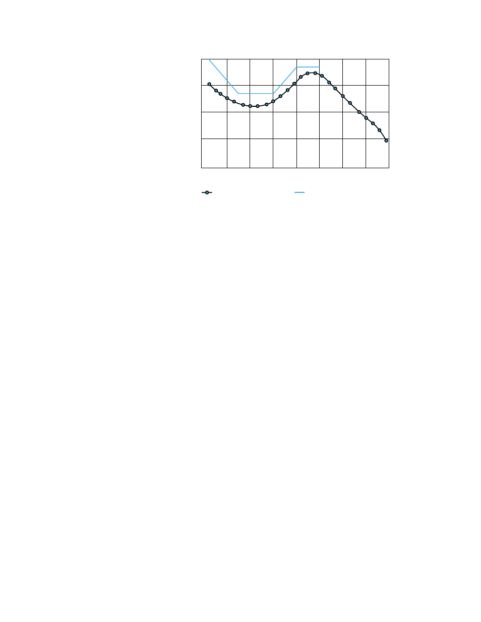
Time Domain Stability
OPTIONAL 16-CHARACTER FRONT
PANEL DISPLAY
Available options include a built-in front panel
display. The standard 58503B GPS time and
frequency reference receiver does not include
a display. While a display is not necessary, it
may be convenient to track the receiver’s
progress during installation and startup by
monitoring the satellites being tracked,
location, time, and other parameters.
OPTIONAL 1 PP2S OUTPUT
(EVEN-SECOND OOUTPUT)
An even-second (1 PP2S) output is available
as an option to the 58503B. The even-second
output option provides one pulse every other
second, synchronized to the even seconds in
GPS time. This is the reference time used in
CDMA base stations. GPS even-second pulses
from the 1 PP2S option are used to synchronize
the Agilent 8921A (Option 600) and the Agilent
8935A cellular base station test sets.
Synchronizing the test set from an independent
source permits remote base station testing
and independent base station frequency and
time reference accuracy checks.
ANTENNA AND CABLING
INFORMATION
The 58532A GPS L1 Reference antenna is
recommended to ensure specified performance
of the 58503B. For optimum performance,
the antenna should be installed in a location
which gives it a clear view of the entire sky.
TYPE
• Active antenna
• Power supplied to the
5 volts nominal
antenna by the 58503B
50 mA max
ANTENNA CONNECTOR (58503B)
• Type
N jack (female).
ANTENNA CABLE
• 58521A cables are recommended. These cables are
LMR 400 with Type-N connectors (male) on both ends.
A variety of lengths are available.
ADDITIONAL ACCESSORIES
• 58502A broadband distribution amplifier; provides
12-Channel broadband (0.1 to 10 MHz) sine wave distribution.
• 58535A/36A/17A GPS L1 signal distribution
amplifiers/splitters allows multiple receivers (2, 4, or 8)
to share a single antenna.
• 58529A GPS line amplifier with L1 bandpass filter;
provides the gain to overcome cable loss and protection
against noise and interference signals.
• 58530A GPS L1 bandpass filter; provides protection
against noise and interference signals
• 58538A/ 58539A lightning arrestors; provides protection
against nearby lightning strikes.
58503B SPECIFICATIONS AND CHARACTERISTICS
GPS RECEIVER FEATURES
GENERAL SPECIFICATIONS
• Eight channel, parallel tracking GPS engine
• C/A Code, L1 Carrier
• SmartClock/ Enhanced GPS
• Optional DC power operation available
10 MHz Output Specifications (with SA on)
LOCKED
• Frequency Accuracy: Better than 1
×
10
-12
, for a one day average, 0 ºC to 50 ºC.
UNLOCKED
• Holdover aging:
<
1
×
10
–10
per day average frequency change in 24 hours of
unlocked operation. (See Notes 1 and 2.)
PHASE NOISE (LOCKED)
• Offset From Signal (Hz)
SSB Phase Noise (dBc)
1
-85
10
-125
100
-135
1000
-140
10000
-145
TIME DOMAIN STABILITY (LOCKED)
(See Figure 3)
• Averaging Time Seconds
Root Allan Variance
0.01
1.5
Ч
10
–10
0.1
1.5
Ч
10
–11
1
5
Ч
10
–12
10
5
Ч
10
–12
100
5
Ч
10
–11
1000
5
Ч
10
–11
SUPPLEMENTAL INFORMATION
• Waveform
Sine wave
• Amplitude
>
1.7 volts p-p (+8 to +10 dBm) into a 50
Ω
load
• Harmonic Distortion
<
–25 dBc (Typical)
• Non-harmonic signals
<
–80 dBc (Typical)
• Source impedance
50
Ω
(nominal)
• Coupling
AC
• Connector
BNC
TIME DOMAIN STABILITY
Locked to GPS
TYPICAL PERFOMANCE
SPECIFICATION
SAMPLE TIME (SECONDS)
ROO
T
ALLEN
V
ARIANCE
.01
1 x 10
-14
1 x 10
-13
1 x 10
-12
1 x 10
-11
1 x 10
-10
0.1
1
10
100
1000
10000
100000
1000000