The synthesized sweep generator, The smr as an upconverter, The ¸smr as an upconverter – Atec Rohde-Schwarz-SMR Series User Manual
Page 5: Db v v mv db (m), Max 50 w reverse power made in germany, Enter, I channel q channel, Microwave signal generator ¸smr
Microwave Signal Generator ¸SMR
5
The synthesized sweep
generator
Analog ramp sweep option
The analog ramp sweep mode corre-
sponds to the analog sweep of classic
sweep generators except that the sweep
is fully synchronized over the complete
range. In this way, the excellent fre-
quency accuracy of digital step sweeps is
achieved on the whole, and this at much
higher sweep rates of min. 600 MHz/ms
at frequencies >2 GHz.
In conjunction with scalar network ana-
lyzers or suitable spectrum analyzers,
realtime adjustment of microwave filters
can be performed, for example.
To mark important frequency ranges such
as filter bandwidths or the position of
attenuation poles, the ¸SMR has 10
user-selectable frequency markers which
can be output as pulse markers at the
marker output (TTL level) or alternatively
modulated on the RF level as level mark-
ers (level reduction of 1 dB).
The use of the ¸SMR in conjunction
with a scalar network or spectrum ana-
lyzer is illustrated by the figure at the
bottom of page 4.
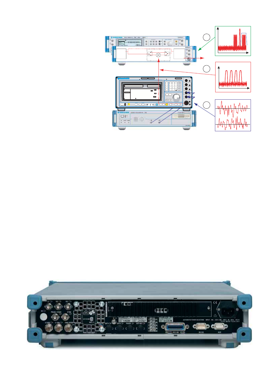
The ¸SMR as an upconverter
IF input option
Vector signal generators such as the
¸SMIQ generate all types of digitally
modulated signals up to 6.4 GHz. To gen-
erate signals up to 40 GHz, the ¸SMR
offers upconversion capability by means
of the IF input option. A typical applica-
tion is shown by the figure above. The I/Q
Modulation Generator ¸AMIQ sup-
plies the I and Q signals (1) required for
modulating the Vector Signal Generator
¸SMIQ.
The modulated RF signal of the
¸SMIQ (2) is applied directly to the IF
input of the ¸SMR. At the RF output
of the ¸SMR, the converted, digitally
modulated signal of the ¸SMIQ is
brought out (3). In the example illustrated
above, the selective circuits of the DUT
separate the wanted signal from
unwanted components generated during
upconversion.
Alternatively, suitable external bandpass
filters can be used.
SIGNAL GENERATOR
DATA INPUT
MENU / VARIATION
STBY
ON
QUICK SELECT
dB V
V
mV
dB (m)
Ω
MAX 50 W
REVERSE POWER
MADE IN GERMANY
DATA
CLOCK
CLOCK
I
Q
BIT
SYMBOL
RF 50
300kHz ... 3.3GHz
SMIQ 03
1084.8004.03
PRESET
LOCAL
ERROR
L E V E L
FREQ
S A V E
RCL
RETURN
SELECT
HELP
STATUS
MOD
ON/OFF
RF
MENU 1
ASSIGN
MENU 2
ON/OFF
1
2
3
4
5
6
7
8
9
G
M
k
m
n
x
1
ENTER
0
.
-
.
STATE
POWER RAMP CONTROL
----- Global for VECTOR MOD + DIGITAL MOD + DIGITAL STD --------
IMPAIRMENT STATE
LEAKAGE
IMBALANCE
QUADRATURE OFFSET
IQ SWAP
CALIBRATE
FREQ
10 0. 000 00 0 0
MHz
LEVEL
- 30.0
dBm
OFF ON
OFF EXT_ANALOG
OFF ON
0 %
0 %
0 deg
NORM INV
FREQUE NCY
LEVEL
ANALOG MOD
VECTOR MOD
DIGITA L MOD
DIGITA L STD
LF OUT PUT
SWEEP
LIST
MEM SE Q
UTILIT IES
I channel
Q channel
1
2
3
Mechanical RF relays
Step
Attenuator
¸
SMR-B15/-B17
Without ¸SMR-B23/-B24/-B25
With
¸SMR-B23/-B24/-B25
Internal
synthesizer
LO
RF
IF
¸SMR as an upconverter for digitally modulated signals