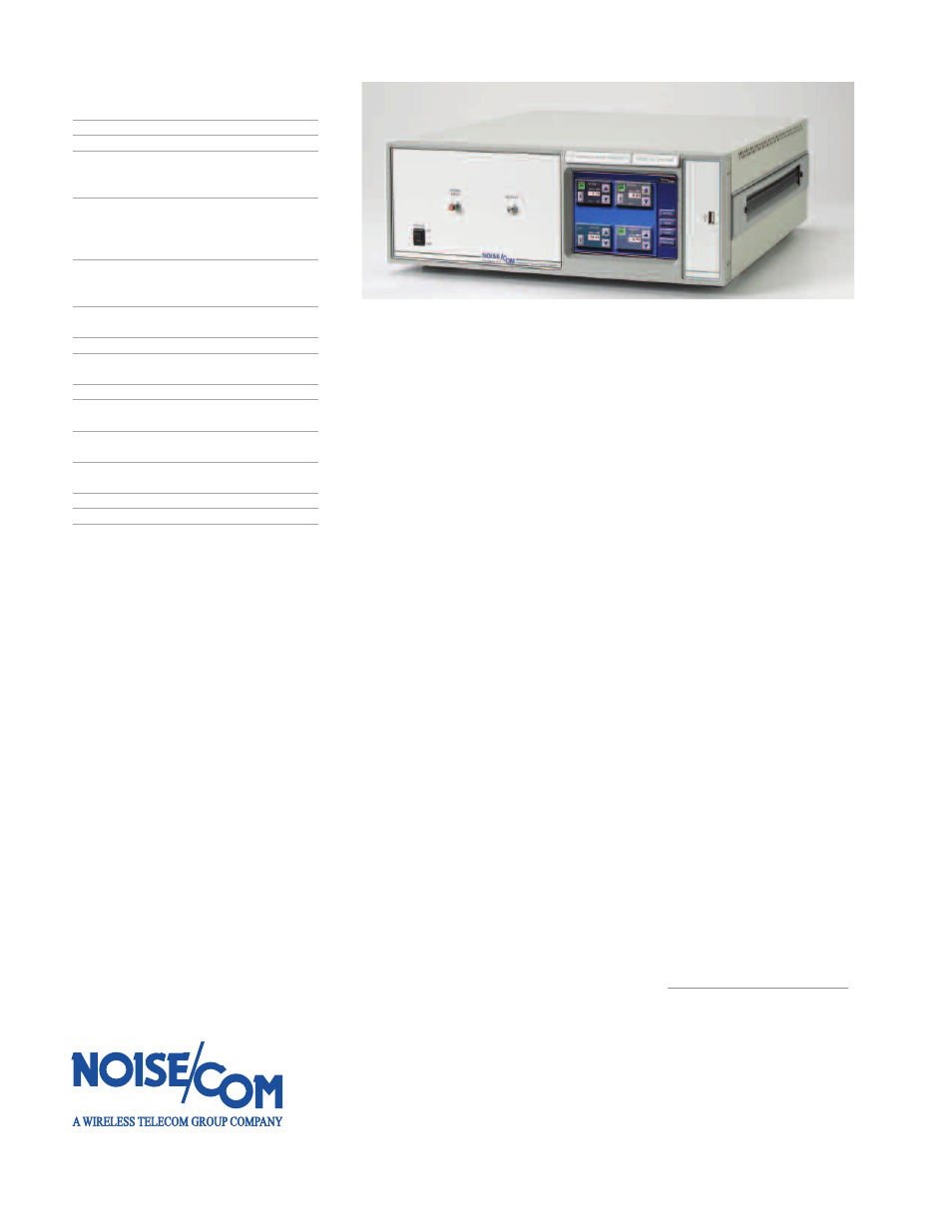
Options – Atec Noise-Com-UFX7000 Series User Manual
Page 4
Options
Option number
Description
U7opt01
N female output connector
U7opt02
BNC female output connector
U7opt03
0 to 127.9 dB noise
Attenuator in 0.1 dB steps
instead of 127 dB in 1 dB steps
†
U7opt04
Switch elements,
2 X SP6T for 4 filter paths,
1 thru-path, 1 termination
(filters are optional)
U7opt06
75 Ohm output impedance
(6 dB loss in the noise path and
12 dB loss in the signal path)
U7opt07
Combiner for input signal
(6 dB loss in noise and signal paths)
U7opt08
Double output terminals (switched)
U7opt09
Custom frequency, power,
or flatness requirement**
U7opt10
Line power 230 VAC, 50 Hz
U7opt11
RS-232 in addition to standard
IEEE-488 interface
U7opt12
0 to 127 dB signal
Attenuator in 1 dB steps*
U7opt13
0 to 127.9 dB signal
Attenuator in 0.1 dB steps
†
U7opt15
Optional 19” rack mounts brackets
U7OPT16
GPIB IEEE-488
†
N/A for UFX7218A and UFX7240A (0 to 79.9 for UFX7124A and
UFX7126A)
* U7opt07 must also be included when ordering this option,
0 to 79 dB above 2 GHz
** Consult factory for pricing and availability
N
/U
FX
70
0
0
/0
6
0
6
/E
N
© Copyright 2006
Noise Com
(A Wireless Telecom Group Company)
All rights reserved.
Note: Specifications, terms and
conditions are subject to change
without prior notice.
25 Eastmans Road
Parsippany, NJ 07054 U.S.A.
Phone:
+1-973-386-9696
Fax:
+1-973-386-9191
Email:
Web site: www.noisecom.com