Model 4200 specifications, Auto mode, Powerful transient generator – Atec NHResearch-4200 User Manual
Page 3: Programability, Measurements, Additional features, Operating contour
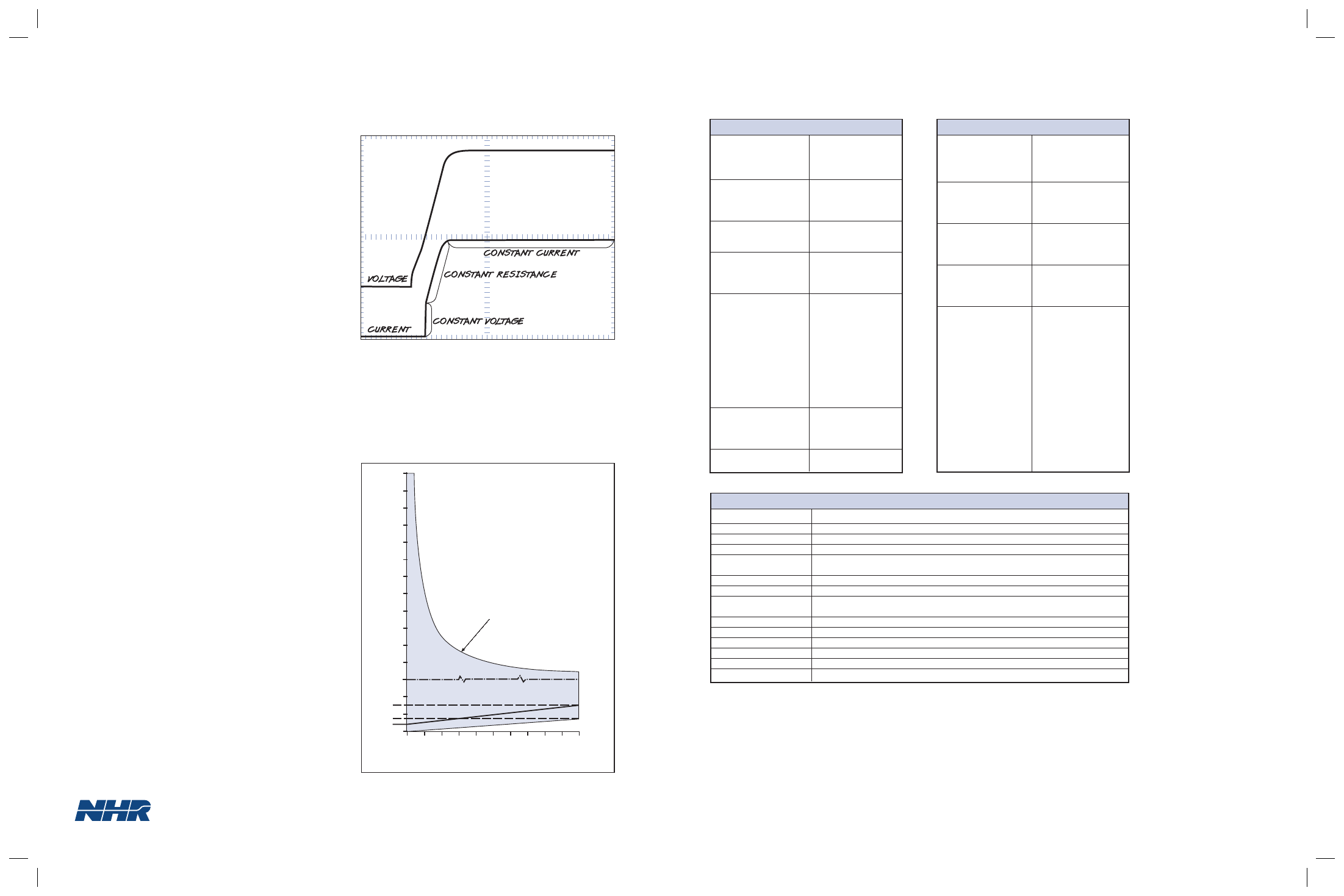
AUTO MODE
The 4200 contains a unique Auto Mode that pro-
vides glitchless automatic switching between CR,
CC, CV and CP limits. Previously challenging tests
that are now made possible include turn-on into a
CR load, confirming the complete V-I curve for
lithium-Ion battery chargers, and preventing device-
under-test blowup should a protection circuit fail.
POWERFUL TRANSIENT GENERATOR
A greatly expanded range of single burst or continu-
ous waveforms are now possible through the built-in
waveform/transient generator. Almost any waveform
can be created with up to100 programmable steps.
Waveforms can be programmed in the CV, CP and
CR modes as well as the customary CC mode.
COMPATIBLE WITH THE HIGHLY FLEXIBLE POWER
MODULE SUBSYSTEM
Within the mainframe power module chassis, the
Model 4200 may be combined with Model
4100/4110 loads as well as 6000/6100 Series DC
sources. The 4200 is also software parallelable,
which allows real time reconfiguration of larger, vir-
tual loads. In this manner, the load creates another
dimension of power module flexibility that assures
adapting to new numbers of outputs and power level
needs in the future.
MODEL 4200 SPECIFICATIONS
PROGRAMABILITY
Constant Current
Ranges
0 to 0.6, 6.0, 60 A
Accuracy
0.06% + 0.06%
Resolution
0.025%
Constant Voltage
Ranges
0.15 to 6.0, 60, 120 V
Accuracy
0.05% + 0.05%
Resolution
0.025%
Constant Resistance
Ranges
0.02 to 5 k
⍀
Accuracy
2%
Constant Power
Ranges
0 to 40, 400 W
Accuracy
1% + 1%
Resolution
0.025%
Transient Generator
Pulse
Current Settings
1 to 100
Total Period
50 µSec to 1 Sec
Delay between Settings
20 µSec to 20 Sec
Resolution
10 µSec
Accuracy
1% ± 5 µSec
Modes
Single burst, continuous
Slew Rates_
2
Ranges
0.6, 6.0, 60A
Maximum
0.03, 0.6, 12A/µSec
External Modulation
Bandwidth
DC to 25 kHz
Voltage
0 to 10 V
Accuracy
5% FS
Short Circuit
Resistance
0.012
⍀ @ 60 A
MEASUREMENTS
DC Current
Ranges
0 to 0.6, 6.0, 60 A
Accuracy
0.05% + 0.05%
Resolution
0.002%
DC Voltage
Ranges
0 to 6.0, 60, 120 V
Accuracy
0.01% + 0.02%
Resolution
0.002%
Power
Ranges
0 to 3.6, 36, 72, 360 W
Accuracy
0.06% + 0.07%
Resolution
0.005%
DIN and Trigger Timing
Range
To 58 years
Accuracy 0.05%
± 100µSec
Resolution
100 nSec
Waveform Capture
Bandwidth
DC to _
1/4
of sample rate
Accuracy 1%
Digitizing Rate
100 to100K Samples/Sec__
3
Memory
256K Samples__
3
Resolution
0.0015%
Triggering
From Mainframe
Measurements
Voltage, Current, Overshoot,
Rise Time, Fall-Time,
Settling Time, Hold-Up
Time, AC RMS, AC+DC
RMS, Trigger-In-Time,
DIN Time, DIN State &
Time
ADDITIONAL FEATURES
Isolation
±500VDC between input and chassis ground
Remote Voltage Sense
2VDC max drop between sense and load input
OVPS Relay
DPDT, 5 A, isolated control
Self Test
Power-up self-test of all major functions including each output transistor
Performance Monitoring
Continuous checking of performance parameters and appropriate error messages
when necessary
Calibration
Closed cover, all adjustments made in software and stored in EEPROM
Protection
OP, OC, OV, OT and Reverse Voltage
Trigger Output
To initiate an external measurement device and synchronized to programmed load
current step
Current Monitor
0 - 10 V external signal appropriate to 100% current for the selected range
Control
RS 232 , RS485
Size (HWD)
4 3/4 x 2 1/2 x 18 in. / 120.7 x 63.5 x 457.2 mm
Weight
Module - 6.6 lbs / 3.0 kg., Chassis - 21 lbs / 9.5 kg
Operating Temperature
0 - 50º C, all specifications apply at 23 ± 5º C
Input Power
115/230 VAC, 1Ø
__
1
All accuracies ± (% of Set/Reading + % of Range). All resolutions % of Range
__
2
Voltage and Current Slew Rates are in the CC mode and can be programmed separately
__
3
Single channel capture. Simultaneous Voltage and Current captures would halve sample rate and memory available.
..........................................................................................................................
..........................................................................................................................
..........................................................................................................................
..........................................................................................................................
..........................................................................................................................
..........................................................................................................................
..........................................................................................................................
..........................................................................................................................
..........................................................................................................................
........................................................................................................................................................
........................................................................................................................................................
........................................................................................................................................................
........................................................................................................................................................
........................................................................................................................................................
........................................................................................................................................................
........................................................................................................................................................
POWER SUPPLY TURN-ON VOLTAGE & CURRENT
WAVEFORMS IN AUTO MODE
50 KS/SEC
50 KS/SEC
10.000 mS/div
Wf1, Chn 001, 5 V/div.
Wf2, Chn 004, 500 mA/div.
Wf1 = Vout; Wf2 = lout
Trigger: WF 1, Rising @ 800.000 mV, DC Coupled
120
110
100
90
80
70
60
50
40
30
20
10
3
2
1
0
0 6 12 18 24 30 36 42 48 54 60
1.5
0.7
0.4
VOL
TS
AMPS
SCALE CHANGE
CR MODE
ONLY
300W Constant Power
NH Research, Incorporated
16601 Hale Avenue, Irvine, California 92606
Tel: 949-474-3900 • Fax: 949-474-7062
E-mail: [email protected]
1
OPERATING CONTOUR