Atec Haefley-PEFT4010 User Manual
Page 2
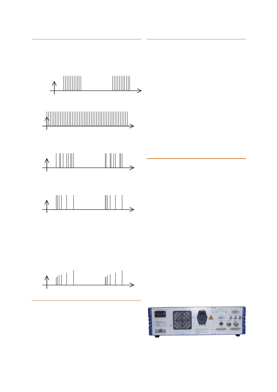
B u rs t Mo d es
On the PEFT 4010 instrument five different burst
modes can be selected.
1.
Normal: Bursts are generated as defined
in IEC 61000-4-4.
U
2.
Continuous: The spikes are generated
continuously with the selected frequency.
U
t
3.
Random: The spike frequency changes
within a burst between 16% and 100% of
the entered value.
U
t
4.
Real: The spike frequency is changed
from the entered value to 16% within a
burst. Burst amplitude remains constant.
U
t
5.
Real5 / Real100: Spike frequency
reduces within a burst from 100% to 16%
and simultaneously the amplitude
increases from ca. 50% to 100%. The
nominal spike frequencies at the start of a
burst packet are fixed at 5 kHz or 100 kHz.
This feature is only available when the
relevant option is integrated in the PEFT 4010
hardware.
U
t
R e m ot e C on t r ol S o f t w a r e
( WinFEAT&R)
The control software (WinFEAT&R
©
) can be installed in
the Microsoft
®
Windows 95 or higher environments and
can be used to control equipment for EFT (IEC 61000-4-
4), SURGE (IEC 61000-4-5), AC Magnetic fields (IEC
61000-4-8) and Dips or Interrupts (IEC 61000-4-11) etc.
C o up li n g/ D ec ou p li ng N e tw or k
( C D N )
A single phase Coupling/Decoupling Network (CDN)
is built into the PEFT 4010 which enables coupling
of the EFT impulses into a single phase mains
network.
If it is necessary to inject EFT Impulse into a three
phase mains system, the PEFT 4010 can be used
together with an external three phase CDN (up to
100A per phase) with coupling path selection either
controlled directly from the PEFT 4010 or manually.
Injection of EFT impulses into signal and control
cables is required by IEC 61000-4-4. The PEFT 4010
has a direct high voltage output connector for use
with the coupling clamp IP4A. The IP4A fulfils all the
requirements of IEC 61000-4-4.
Bursts can also be coupled directly into electronic
circuits using the optional electric and magnetic field
generation probes, mainly used for failure detection.
I n te rf a c i ng
EUT Failed
Connect pass/fail detection hardware to this BNC
input and the EUT (Equipment Under Test)
condition, as determined by specific EUT supervision
hardware, is added to the database of test
information and finally the log file. EUT condition
can also be used to determine the test course.
Trigger In
External signals can be used to trigger impulse
generation to a particular event.
Sync In
Impulses can be synchronised to any external cyclic
signal with a high degree of accuracy.
PESD Control
This interface can be used to attach the PESD 1610
generator to the PEFT 4010. The PEFT 4010 is able
to control and document the ESD pistol operation.
P90 Extension
The P90 interface is a self developed standard used
for communication between test instruments. The
primary function of this interface is to control the
automatic three phase CDN which is available as an
option.
Rear panel view of the PEFT 4010