Compact immunity test system cit-10 – Atec Frankonia-CIT-10 User Manual
Page 3
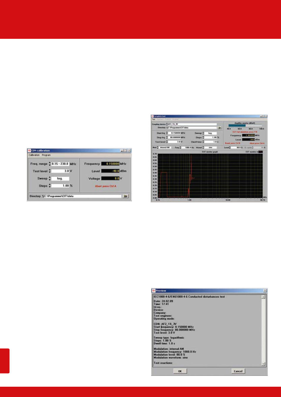
CDN-Calibration
The CDNs (Coupling/Decoupling Networks) serve to inject the
test voltage into the lines to be tested and/or to decouple any
connected peripheral equipment from the EUT. The charac-
teristics of the CDNs as well as of the power amplifier are not
absolutely linear over the whole frequency range, i.e. the
amount of power required to generate a constant test voltage
over the whole frequency range varies slightly, depending on
the frequency. In the calibration run, the frequency-depen-
dent output level of the signal generator, which is necessary
for a constant test voltage, will be determined and stored in
the software, together with the defined frequency range and
the desired test voltage. The data records thus created may
then be stored and recalled for tests.
Self-Calibration
When selecting this menu option, the test equipment will per-
form a self-calibration. In this case, the output of the signal
generator must be connected to the input of the voltmeter.
Test
The menu option
test, e.g. start and stop frequency, step width and test voltage
are made automatically via the calibration file of the selected
coupling unit. It is now possible to decide whether the test is
to be performed exactly according to these pre-settings, i.e.
exactly as in the calibration, or whether modifications of the
pre-settings shall be admissible. If the calibration run was per-
formed, for example, for a test voltage of 10 V, and the test is to
be performed now with 3 V without having to perform a new
calibration run for this purpose, this can be done by selecting
menu item
Is a suitable measuring instrument connected to the specified se-
rial port of the CIT-10, EUT can be monitored automatically. Data
are shown graphically. During all test routines the amplifier out-
put is monitored in a bar display. This guarantees correct tests.
In the case of
complete selected frequency range; in this case the test frequency is in-
creased by the control software according to the selected step width and
the entered dwell time. If there is a malfunction of the EUT, the test may
be stopped at any time. It is then possible to either increase or reduce
the frequency by any number of steps, as well as to switch on and off
the modulation and test voltage. Besides, a description of the malfunc-
tion occurred may be entered in a comment line which is included in
the test record.
cies. This can be done either with a fixed test voltage or, optionally, with
a ramp function. In case of the ramp function, the start and stop voltage,
the step width by which the test voltage is to be increased, as well as the
dwell time between the individual steps may be preset by the tester.
The standard
gram which shows the test results. In the head of the protocol the date
and time are taken over from the computer; in addition, details like
temperature, air humidity, tester, as well as testing set-up and EUT,
may be registered. The protocol may be printed directly. It is also pos-
sible to edit the protocol individually.
acc. to IEC/EN 61000-4-6 / ISO 11452-4 / MIL-STD 461E
Compact Immunity Test System CIT-10,
10kHz - 400MHz
PAGE // 16