Efg-3/efg-3b, Series, E-field generating antenna – Atec IFI-EFG-3-EFG-3B User Manual
Page 2
The EFG-3 radiating system is small enough to be physically
manageable and portable, but large enough to provide efficient
conversion of RF power into a uniform electric field over a
useful physical area. This high efficiency is obtained in several
ways. As shown in Fig. 1, broadband transformers are used to
step up the 50 ohm input impedance to 200 ohms. This is the
design impedance of the terminated loop antenna system.
Voltage between the upper and lower edges of the antenna
system then becomes approximately twice that of the driving
source. For example, a 25 watt power source will cause a 54
volt rms differential, after passing through the step up
transformer.
Since the upper and lower edges of the antenna are spaced
at 1 meter, any point in the plane of the antenna (and between
these two edges) will have an E-Field gradient of
twice the applied voltage, measured in volts per
meter.
Furthermore, the upper and lower edges of the
EFG-3 are equipped with pivoting projections that
can be used to form an extended transmission line
mode of operation at the outer surface of the anten-
na. Small objects (less than 1/2 meter in size) can
be placed between the opening and will be sub-
jected to the corresponding field intensity as a
function of the applied voltage.
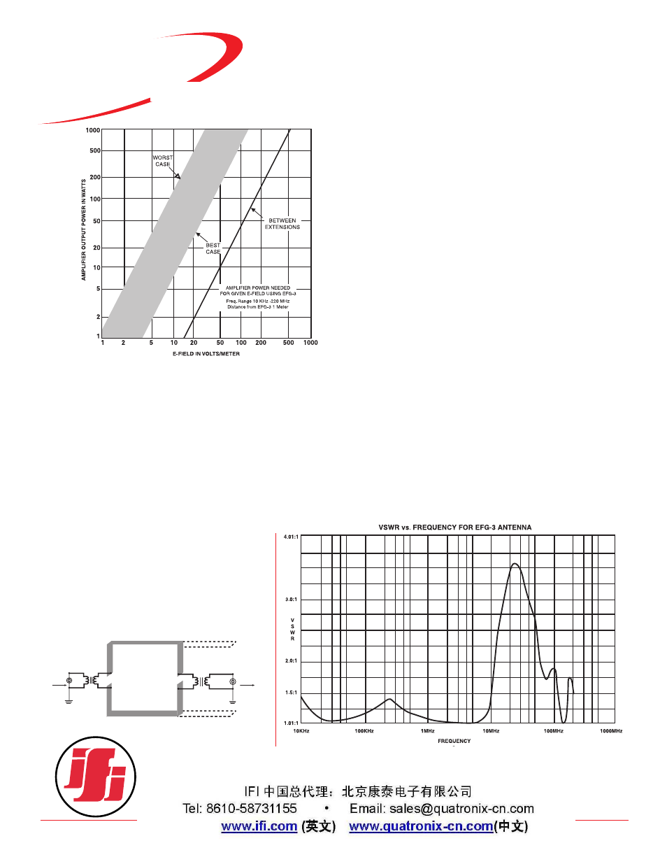
For objects too large to be placed between these extensions,
the EFG-3 may be used in an E-Field radiating mode. Fig. 2
shows the power required to generate a given field strength at a
distance of 1 meter from the plane surface of the antenna. E-
Field radiation is a non-linear function of frequency, which
accounts for the wide band of related power and field strength,
taking into account best and worst case conditions. Reflections
can cause perturbations in the field distribution and widen the
effective curve width for a given power input and desired E-Field.
In selecting a power source for use with the EFG-3,
allowances should be made for these effects. The source should
be capable of supplying sufficient power for the worst case con-
ditions, under given use for the full frequency spectrum.
Furthermore, there should be sufficient control over the power
source to permit attenuation for use under best case conditions.
Unlike similar high power antennas intended for
EMC/Susceptibility testing, the unused power is not dissipated in
the EFG-3 itself. A second set of broadband transformers are
employed to return the balanced loop 200 ohm termination
impedance to an unbalanced 50 ohm output; this allows system
termination with a conventional coaxial load. This output port
can be connected directly to a termination capable of dissipat-
ing the appropriate power levels.
The actual antenna pattern is a cardioid with the null at the
feed point where the antenna attaches to its horizontal pipe sup-
port. Both input and output connectors are located near this
point. The input port of the EFG-3 system does not present an
objectionable VSWR for most normal wide band laboratory
grade amplifiers over the full rated frequency spectrum. Fig. 3
shows a VSWR plot with respect to frequency for a standard
installation.
SERIES
INSTRUMENTS FOR INDUSTRY INC.
903 South Second Street, Ronkonkoma, NY 11779
Tel: 631-467-8400 • Fax: 631-467-8558 • E mail: [email protected]
www.ifi.com
EFG-3 1000 watts
EFG-3B 2000 watts
E-Field Generating
Antenna
EFG-3/EFG-3B
POWER
IN
1:4
Z TRANSFORMER
TO
LOAD
4:1
Z TRANSFORMER
Fig. 1
Fig. 2
Fig. 3