Atec Endevco-2680M1-M7 User Manual
Features description, M" number gain range input pulse residual noise, Dash no. lower cutoff freq
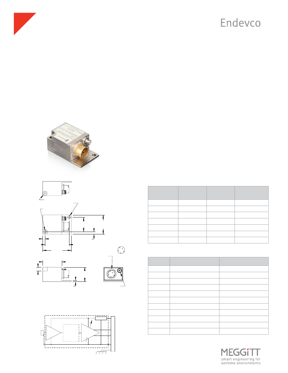
The Endevco models 2680M1-XXX through 2680M7-XXX Charge
Amplifiers are designed for use with piezoelectric transducers
and are suitable for airborne applications. Hybrid microcircuit
construction results in small size, ruggedness and low power
consumption. The airborne charge amplifiers have an output
voltage proportional to the input charge. As a result, the ampli-
fier sensitivity is not appreciably affected by the capacitance of
the input cable.
The use of modular construction techniques permits great
versatility in gain and filter choices. This unit has two outputs, a
biased output and an unbiased output. Both outputs are adjust-
able with a common gain control. The M1 through M7 defines
the charge gain per Table 1.
The -XXX describes the upper cutoff frequency (-5% point) per
Table 2. For example, a -101 has a low pass filter which is flat up
to 100 Hz, a -502 has a low pass filter which is flat up to 5000 Hz.
• For use with piezoelectric transducers
• Small, rugged, light weight
• Dual outputs, biased and unbiased
• Adjustable gain
• Optional low pass filter
Model 2680M1-M7
Airborne charge amplifiers
Features
Description
Variable
Gain
Amplifier
Optional
2 Pole
Butterworth
Low Pass
Filter
Charge
Convertor
Regulator
A
+28 VDC
B
C
Unbiased
Output
Biased
Output
Signal &
Power
Ground
D
E
Case GND
Viking
VR5/4AG15
10-32 THD
Input
Connector
GAIN ADJUST
.154 (3.91) DIA 2 PL
.755 (19.18)
.745 (18.92)
1.000
(25.40)
.060
(1.52)
COUNTERBORED FOR
#6 CAP SCREW
.750
(19.05)
OUTPUT (VIKING
#VR5/4AG15 OR
EQUIVALENT)
PIN FUNCTIONS
A - +28 V DC
B - UNBIASED OUTPUT
C - BIASED OUTPUT
D - SIG & PWR GND
E - CASE GND
INPUT (MICRODOT #51-49 OR
EQUIVALENT) 10-32 UNF-2A THD
.200
(5.08)
.120
(3.05)
1.500
(38.10)
.120
(3.05)
1.000
(25.40)
1.255 (31.75)
1.245 (31.62)
D
C
B
A
E
STANDARD TOLERANCE
INCHES (MILLIMETERS)
.XX = +/- .02 (.X = +/- .5)
.XXX = +/- .010 (.XX = +/- .25)
Table 1: Gain ranges
"M" number
Gain range
Input pulse
Residual noise
[mV/pC]
[pC]
[mV rms]
M1
0.1 to 1.0
50 000
1.5
M2
0.2 to 2.0
25 000
1.5
M3
0.5 to 5.0
10 000
1.5
M4
1.0 to 10.0
5000
1.5
M5
2.0 to 20.0
2500
1.5
M6
5.0 to 50.0
1000
1.5
M7
10.0 to 100
500
2.0
Table 2: Frequency response
Dash No. Lower cutoff freq.
[-5%]
Upper cutoff freq.
[-5%]
None
5 Hz
20 kHz (10 kHz for M7)
101
5 Hz
100 Hz
201
5 Hz
200 Hz
501
5 Hz
500 Hz
102
5 Hz
1 kHz
202
5 Hz
2 kHz
502
5 Hz
5 kHz
103
5 Hz
10 kHz
203
5 Hz
20 kHz (10 kHz for M7)
402
5 Hz
4 kHz
250
5 Hz
25 Hz
cmyk