Performance specifications, Introduction, Performance specification – Atec Anritsu-MS2026A User Manual
Page 2: General specifications, Power monitor - detectors, Frequency, Return loss, Vswr, Cable loss, Port phase
Performance Specifications
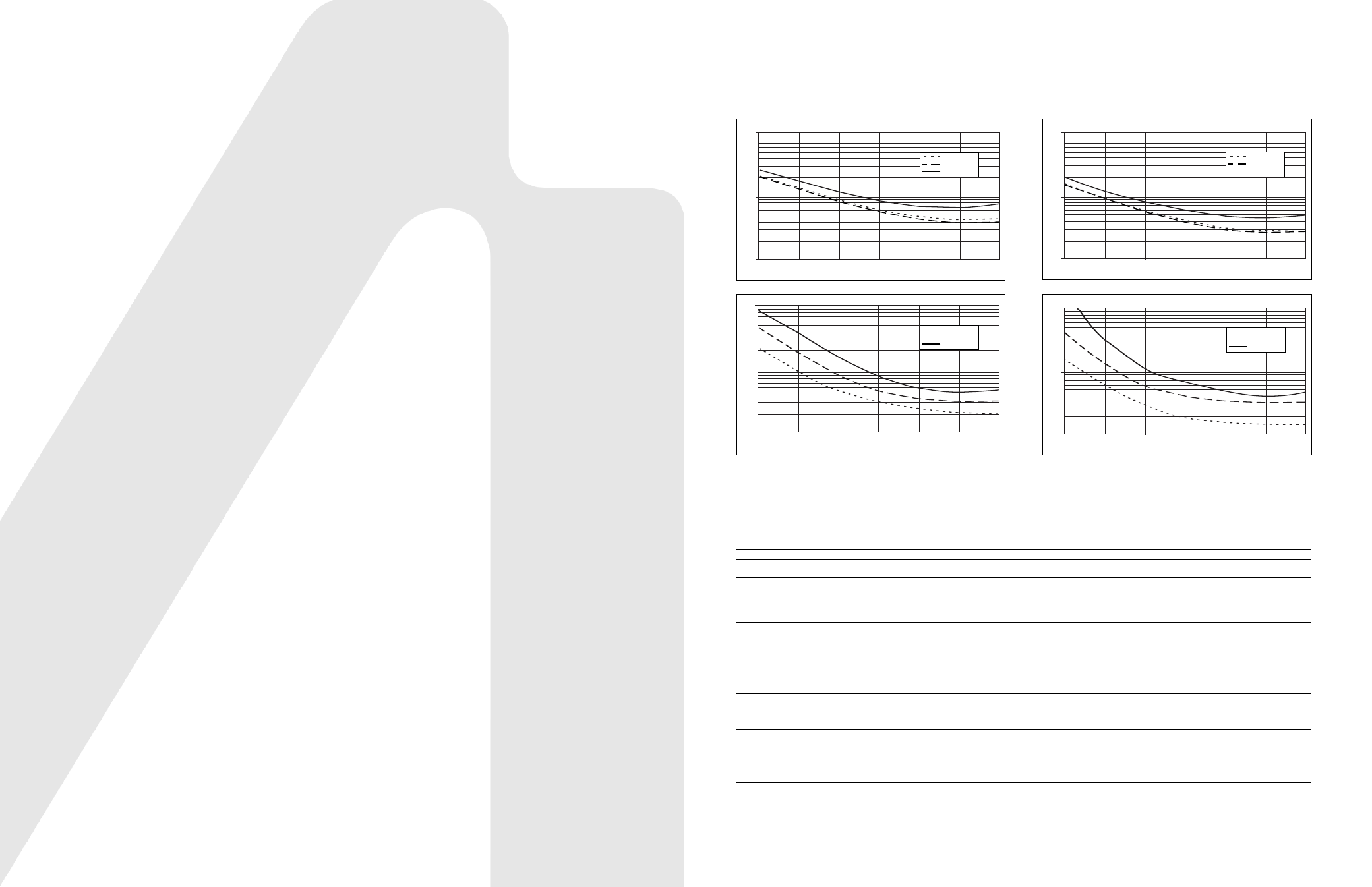
The following graphs provide measurement uncertainty at 23°C after vector correction for the standard N connector type.
The errors are worse-case contributions of residual directivity, source match, frequency response, network analyzer dynamic range,
and connector repeatability. For the 1-path 2-port measurements, transmission tracking, crosstalk and physical load match terms
were added. Calibration components OSLN50-1 were used.
Power Monitor - Detectors
Model
Frequency Range
Impedance
Return Loss
Input Connector
Frequency Response
5400-71N50
0.001 to 3 GHz
50
Ω
26 dB
N(m)
±0.2 dB, <1 GHz
±0.3 dB, <3 GHz
5400-71N75
0.001 to 3 GHz
75
Ω
26 dB,
<2 GHz
20 dB,
<3 GHz
N(m)
±0.2 dB, <1 GHz
±0.5 dB, <3 GHz
560-7A50
0.01 to 18 GHz
50
Ω
15 dB, <0.04 GHz
22 dB, <8 GHz
17 dB, <18 GHz
GPC-7
±0.5 dB, <18 GHz
560-7N50B
0.01 to 20 GHz
50
Ω
15 dB, <0.04 GHz
22 dB, <8 GHz
17 dB, <18 GHz
14 dB, <20 GHz
N(m)
±0.5 dB, <18 GHz
±1.25 dB, <20 GHz
560-7S50B
0.01 to 20 GHz
50
Ω
15 dB, <0.04 GHz
22 dB, <8 GHz
17 dB, <18 GHz
14 dB, <20 GHz
WSMA(m)
±0.5 dB, <18 GHz
±1.25 dB, <20 GHz
560-7S50-2
0.01 to 26.5 GHz
50
Ω
15 dB, <0.04 GHz
22 dB, <8 GHz
17 dB, <18 GHz
14 dB, <26.5 GHz
WSMA(m)
±0.5 dB, <18 GHz
±1.25 dB, <26.5 GHz
560-7K50
0.01 to 40 GHz
50
Ω
12 dB, <0.04 GHz
22 dB, <8 GHz
17 dB, <18 GHz
15 dB, <26.5 GHz
14 dB, <32 GHz
13 dB, <40 GHz
K(m)
±0.5 dB, <18 GHz
±1.25 dB, <26.5 GHz
±2.2 dB, <32 GHz
±2.5 dB, <40 GHz
560-7VA50
0.01 to 50 GHz
50
Ω
12 dB, <0.04 GHz
19 dB, <20 GHz
15 dB, <40 GHz
10 dB, <50 GHz
V(m)
±0.8 dB, <20 GHz
±2.5 dB, <40 GHz
±3.0 dB, <50 GHz
0.025-0.3 GHz
0.3-3 GHz
3-6 GHz
Reflection Magnitude Uncertainty (S21=0)
10
1
0.1
-60
-50
-40
-30
-20
-10
0
l
S11
l
(dB)
E
s
ti
m
a
te
d
U
n
c
e
rt
a
in
ty
(
d
B
)
0.025-0.3 GHz
0.3-3 GHz
3-6 GHz
Reflection Phase Uncertainty (S21=0)
100
10
1
-30
-25
-20
-15
-10
-5
0
l
S11
l
(dB)
E
s
ti
m
a
te
d
U
n
c
e
rt
a
in
ty
(
d
e
g
)
Transmission Magnitude Uncertainty (S11=0)
10
1
0.1
-60
-50
-40
-30
-20
-10
0
l
S21
l
(dB)
E
s
ti
m
a
te
d
U
n
c
e
rt
a
in
ty
(
d
B
)
0.025-0.3 GHz
0.3-3 GHz
3-6 GHz
Transmission Phase Uncertainty (S11=0)
100
10
1
-60
-50
-40
-30
-20
-10
0
l
S21
l
(dB)
E
s
ti
m
a
te
d
U
n
c
e
rt
a
in
ty
(
d
e
g
)
0.025-0.3 GHz
0.3-3 GHz
3-6 GHz
Introduction
VNA Master MS2024A/MS2026A are the most ultra-portable
VNAs on the market. They are designed to make accurate
vector corrected 1-Port and 1-path 2-Port magnitude and
phase measurements from 2 MHz to 4 GHz (MS2024A) and
2 MHz to 6 GHz (MS2026A). VNA Master’s light weight
(6.4 lbs) and three hour battery life time provide you with
the flexibility needed to make VNA measurements anywhere.
Performance Specification
Frequency
Frequency Range:
2 to 4000 MHz (MS2024A)
2 to 6000 MHz (MS2026A)
Frequency Accuracy:
25 ppm
Frequency Resolution
➀
: 10 kHz
Data Points:
Low, Medium, High (137/275/551)
Interference Immunity
➁
:
On-Channel:
+17 dBm
On-Frequency:
+10 dBm (RF Out), +30 dBc RF In
1-Port Power:
High:
0 dBm (typical)
2-Port Power:
High:
0 dBm (typical)
Low:
–35 dBm (typical)
Corrected Directivity
➂
:
42 dB (2 MHz to 6 GHz)
1-Port Accuracy
➂
:
= <0.8 +
|
20 log(1 ±10
-E
∆
/20
)
|
dB, typical
E
∆ = Directivity – Measured Return Loss
System Dynamic Range:
80 dB, 2 MHz to 3 GHz
70 dB, >3 GHz to 5.5 GHz
65 dB, >5.5 GHz to 6 GHz
Return Loss
Range:
0 to 60 dB
Resolution:
0.01 dB
VSWR
Range:
1 to 65
Resolution:
0.01
Cable Loss
Range:
0 to 30 dB
Resolution:
0.01 dB
1-Port Phase
Range:
–180° to +180°
Resolution:
0.01°
Smith Chart
Resolution:
0.01
2-Port Gain
Range:
–120 to 100 dB
Resolution:
0.01 dB
2-Port Phase
Range:
–180° to +180°
Resolution:
0.01°
Distance-to-Fault (DTF)
Fault Resolution (meters):
(1.5 x 10
8
x vp)/
∆F vp is the propagation
constant and
∆F is F2-F1 in Hz
Horizontal Range (meters): 0 to (data points-1) x Fault Resolution
to a maximum of 1500m (4921 ft)
where datapoints = 137/275/551
Vertical Range
(Return Loss):
0 to 60 dB
Vertical Range (VSWR):
1 to 65
RF Power Monitor (Option 5):
Display Range:
–80 to +80 dBm (10 pW to 100 kW)
Detector Range:
–40 to +20 dBm (100 nW to 100 mW)
Offset Range:
0 to +60 dB
Resolution:
0.1 dB or 0.1 W
Accuracy:
±1 dB maximum for >–40 dBm
using 560-7N50B
Bias T (Option 10):
Voltage/Current:
+12 V, 250 or 500 mA steady state
+15 V, 250 or 500 mA steady state
+18 V, 350 mA steady state
+21 V, 300 mA steady state
+24 V, 250 mA steady state
GPS Receiver (Option 31)
GPS Location Indicator
Latitude, Longitude, Altitude and UTC on Display
General Specifications
Languages
Built-in English, Spanish, Italian, French, German, Japanese, Korean,
and Chinese. Can also customize two additional languages using
Master Software Tools.
Memory
Internal memory provides for the storage and recall of more than
1000 traces and setups. The contents of the internal memory can
be copied to and from a removable Compact Flash Card.
Markers
6 markers (Delta marker, peak search, valley search) and Marker Table.
Traces
View Trace, Memory, Trace-Memory, Trace + Memory, Trace and Memory
Limit Lines
Upper and Lower Limit. Each upper and lower limit can consist of
between one and forty segments.
Display
Bright daylight viewable color TFT LCD, Full SVGA, 8.4 in.
Interface Connectors
Type N female RF Out Port and RF In Port (50
Ω)
5-pin Mini-B USB 2.0 for data transfer to a PC
RJ45 Connector for Ethernet 10/100 Base-T
2.5 mm 3-wire headset connector
Remote Programmability Commands
Not available
Power Supply
External DC Input, +12 V, 5A max
ESD Damage Level
10 kV
Maximum Input (Damage Level)
Test Port, Type N:
+22 dBm
RF Detector:
+20 dBm
Impedance
50
Ω
Dimensions
12 x 8 x 3 in. (305 x 203 x 76 mm)
Weight
<6.4 lbs (2.9 kg)
Environment
MIL-PRF-2800F Class 2
Operating:
–10°C to 55°C, humidity 85% or less
Storage:
–51°C to 71°C
Altitude:
4600 meters, operating and non-operating
Safety
Conforms to EN 61010-1 for Class 1 portable equipment
Electromagnetic Compatiblity
Meets European Community requirements for CE marking
➀
If display resolution (Span / (DataPoints-1)) is less than 150 kHz, then frequency resolution only
applies to measurements with RF Immunity set to Normal.
➁
On Channel Interference Immunity is specified at >1.0 MHz of the carrier frequency.
On-Frequency Interference Immunity is specified to within ±10 kHz of the carrier frequency.
➂
All accuracy and directivity specifications apply only when using Anritsu’s precision components.
➃
For data transfer only, remote programmability commands not available.