Est), Uropean, Tandards – Atec Elgar-est User Manual
Page 2: Ester, Pa 1000, Ordering information
Elgar
■
1.800.733.5427
■
858.450.0085
■
Fax 858.458.0267
■
9250 Brown Deer Road, San Diego, CA 92121
■
www.elgar.com
■
email: [email protected]
17
E
UROPEAN
S
TANDARDS
T
ESTER
(EST)
PA 1000
Unique among analyzer systems, the EST
Series PA 1000 performs all measurements
and real-time digital signal processing. The
PC is only used to display the User
Interface which provides control of the
equipment. Other key features of the
analyzer are:
■
Sampling rate of 175,000 samples/s
■
18 bit A-to-D converters
■
24 bit/80 MIPS real-time DSP
■
Optional Discrete Reference
Impedance
■
No range switching required to
measure the full 16 amp range
■
Continuous AC power source
monitoring
■
Front or rear panel EUT power
connections
■
Flickermeter complies with EN 868
and EN 61000-4-15
■
1 year calibration interval
The PA 1000 offers full compliance with
on-board, self contained, computation.
The PA 1000 digital signal processor
performs all computations including
filtering, weighing, FFT’s and DFT’s.
SET-UP
Simple start-up windows provide easy test
set-up fields and EST system control. Each
test configuration can be rerun from the
test template screen and is stored as part
of a test log history file. Class selection
includes A, B, C and D and an auto A/D
feature that enables the analyzer to classify
the equipment during the test. All data is
exportable to spreadsheet applications.
HARMONICS (EN 61000-3-2)
The harmonics graphs and tables are
updated continuously during the test. The
harmonic bar chart displays the harmonic
content of the EUT as well as displaying
the limit for each harmonic specified by the
standard. Absolute and relative harmonic
measurements can be displayed
simultaneously. Worst case measurements
are stored throughout the test and
displayed with pass/fail designation.
The PA 1000 meets
t
he exact requirements
of the EN 61000-3-2, as described in
Annex B.4.2.
Annex B.4.2
Additional requirements for all other
cases, including fluctuating harmonics
a) There shall be no gap, and no overlapping between
successive measuring windows for rectangular
(“uniform”) windows.
FLICKER (EN 61000-3-3)
Pt plot displays the distribution of
instantaneous flicker values. An
innovative dt distribution graph assists
the user in troubleshooting the equipment
under test. This plot displays the
distribution of voltage deviations.
IMMUNITY TESTING
The EST’s AC source generates waveforms
compliant with the following immunity test
standards:
EN 61000-4-11 Voltage Dips, Short
Interruptions and Voltage
Variations (Pre-Compliance)
EN 61000-4-13 Harmonics, Interharmonics
including Mains Signaling
at AC Powerport –
Immunity Test
EN 61000-4-14 Voltage Fluctuation –
Immunity Test
EN 61000-4-17 Ripple on DC Input Power
Port – Immunity Test
EN 61000-4-28Variation of the Power
Frequency - Immunity Test
The EST’s User Interface includes test
routines for each of these immunity tests.
The tests can be executed following a
simple wizard format. All test parameters
can be changed. During all immunity tests
three charts are plotted continually (plot
points updated every 1.5 seconds, user
adjustable) for frequency, VRMS and IRMS.
The short form report contains pass/fail,
calibration data and test configuration (the
minimum information typically required by
regulatory agencies).
Sampling data is provided for harmonics
and flicker, worst case values, and other
data that is useful for troubleshooting and
maintaining historical records for
equipment designers.
IMMUNITY TEST REPORTS
Reports are also generated for the
immunity tests. After each test sequence is
run a note pad screen is automatically
generated. This note pad stores the
operator’s comments and observations for
each sequence. These notes are
automatically logged in the test report in
the test and sequence order. Reports also
contain all test configuration data fields.
Reports and all test data may be down-
loaded for spreadsheet applications for
maximum user versatility.
Note: For more information on the SWAE see page 15.
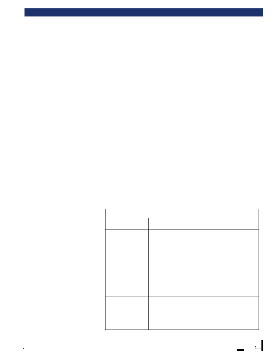
Ordering Information
Model
Output Power
AC Input
Rating
EST 1750-1
1750 VA
1
187-264 VRMS (L-L), 3 wire
EST 1750-2
1750 VA
1
342-457 VRMS (L-L), 4 wire
EST 1750-3*
1750 VA
1
187-264 VRMS (L-L), 3 wire
EST 1750-4*
1750 VA
1
342-457 VRMS (L-L), 4 wire
230 V L-N, Single Phase, 3 wire
EST 3700-1
3700 VA
2
187-264 VRMS (L-L), 3 wire
EST 3700-2
3700 VA
2
342-457 VRMS (L-L), 4 wire
EST 3700-3*
3700 VA
2
187-264 VRMS (L-L), 3 wire
EST 3700-4*
3700 VA
2
342-457 VRMS (L-L), 4 wire
230 V L-N, Single Phase, 3 wire
EST 5250-1
5250 VA
3
187-264 VRMS (L-L), 3 wire
EST 5250-2
5250 VA
3
342-457 VRMS (L-L), 4 wire
EST 5250-3*
5250 VA
3
187-264 VRMS (L-L), 3 wire
EST 5250-4*
5250 VA
3
342-457 VRMS (L-L), 4 wire
230 V L-N, Single Phase, 3 wire
* Power factor corrected
1
1495 VA at 230V output
2
3680 VA at 230V output
3
4485 VA at 230V output
Any model can be ordered with the optional discrete reference impedance in addition to the standard synthesized impedance.