Vds 200b, Vds 200b model configuration, Common technical data – Atec EM-Test-VDS-200B User Manual
Page 2: Technical data vds 200b0, Technical data vds 200b, Technical data vds 200b1, Technical data vds 200b2, Technical data vds 200b3, Technical data vds 200b4, Technical data vds 200b5
EM TEST AG
Tel:
+41 (0)61 717 91 91
Sternenhofstr. 15
Fax:
+41 (0)61 717 91 99
vds200bv110.doc
CH-4153 Reinach
email:
12.07.07
Switzerland
URL
http://www.emtest.com
Page 2/2
VDS 200B
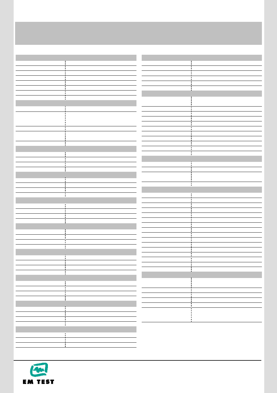
VDS 200B model configuration
VDS 200B0
Voltage Drop Simulator 60V/ 10A
VDS 200B
Voltage Drop Simulator 60V/ 15A
VDS 200B1
Voltage Drop Simulator 60V/ 30A
VDS 200B2
Voltage Drop Simulator 60V/ 50A
VDS 200B3
Voltage Drop Simulator 60V/ 100A
VDS 200B4
Voltage Drop Simulator 60V/ 150A
VDS 200B5
Voltage Drop Simulator 60V/ 200A
Common technical data
Source impedance
Zi = < 10m
Ω
Voltage deviation
< 1V at any load (including inrush current)
recovering 63% of its maximum excursion
within 100us
Ripple voltage
Ur < 0.2Vp-p, frequency min. 400Hz
Bandwidth
Vpp max 16V up to 25kHz
Vpp max 6V up to 50kHz
Technical data VDS 200B0
Output voltage
0V – 60V
Output current continuous
0A – 10A
Output current peak
15A
Technical data VDS 200B
Output voltage
0V – 60V
Output current continuous
0A – 15A
Output current peak
15A
Technical data VDS 200B1
Output voltage
0V – 60V
Output current continuous
0A – 30A
Output current peak
70A for max 500ms
Technical data VDS 200B2
Output voltage
0V – 60V
Output current continuous
0A – 50A
Output current peak
100A for max 500ms
Technical data VDS 200B3
Output voltage
0V – 60V
Output current continuous
0A – 100A
Output current peak
150A for max 500ms
Technical data VDS 200B4
Output voltage
0V – 60V
Output current continuous
0A – 150
Output current peak
150A
Technical data VDS 200B5
Output voltage
0V – 60V
Output current continuous
0A – 200A
Output current peak
200A
Trigger
Automatic
Automatic release of the events
Manual
Manual release of a single pulse
External
External release of a single pulse
Output
DUT Supply +/-
Safety laboratory and high current plugs
Aux IN +/-
To connect an external dc supply for dips
Analog control input
0-10V / 10k
Ω / 0-50kHz
External trigger
5-15V TTL; BNC connector
CRO Trigger
5V TTL-signal for oscilloscope
Test Routines for arbitrary waves
DC source
Max. 60V;
current depending on VDS 200B model
Functions
1. Sine Wave
2. Jump Start
3. Extern
4. GM 9105P Pulse 4
5. Drop and Jump pulse
Standard Test Routines
1. ISO 7637
2. ISO 16750-2
3. Jaso Test 1
Service
Service, Setup, Self test
Interface
Serial interface
RS 232, baud rate 1200 - 19200
Parallel interface
IEEE 488, address 1 - 30
Remote control
To connect external signal generators
0-10V / 10k
Ω / 0-50kHz
General data
Dimensions, weight
19“ / 6HU, app. 49kg for VDS 200B0/B
19“ / 9HU, app. 76kg for VDS 200B1
19“ / 12HU, app. 114kg for VDS 200B2
19“ / 16HU, app. 170kg for VDS 200B3
19“ / 25HU, app. 400kg for VDS 200B4
19” / 34HU, app. 450kg for VDS 200B5
Supply voltage
VDS 200B0
115/230V +10/-15%
VDS 200B
115/230V +10/-15%
VDS 200B1
230V +10/-15%
VDS 200B1
208V (US version)
VDS 200B2
3x440V
VDS 200B2
3x208V (US version)
VDS 200B3/B4/B5 3x440V
VDS 200B3/B4/B5 3x480V (US version)
Fuses
Depending on VDS 200B model
Options
AutoWave
Arbitrary generator for more complex test
requirements
CNA 200B2
Central coupling matrix, 60V/50A
CNA 200B3
Central coupling matrix, 60V/100A
CNA 200B4
Central coupling matrix, 60V/150A
CNA 200B5
Central coupling matrix, 60V/200A
ISMISO
Software to control the test, including
standard library, test report facility and
data conversion generator
Technical data subject to change without notice