Atec Biddle-DET3-2 User Manual
Page 4
DET3 Contractor Series
Earth/Ground Resistance Testers
ART (ATTACHED ROD TECHNIQUE)
TESTING CAPABILITY
The
DET3TC includes the additional testing capability that
we have termed
ART, for Attached Rod Technique. A
nagging problem with traditional ground testing has been
the requirement to “lift” (i.e., disconnect) the utility
connection. Once the grounding conductor (the main
conductor that connects the facility to the ground rod or
grid) has been attached to the grounding electrode, the
utility ground becomes a parallel resistance. The utility
neutral is typically bonded to the ground bus at the
service entrance and this connection, during a ground
test, causes test current to flow back through the utility
ground as well as through the test electrode. Test current
divides according to Law of Parallel Resistance, but the
tester makes its measurement based on total current flow.
The reading is the combined parallel resistance of the on-
site ground and the utility protection. This is a valid
measurement, but not of the test electrode exclusively.
This poses a considerable problem in many common
testing situations. If a commissioning test were required to
determine if design specifications had been met for a new
facility, such a reading would be insufficient. Lightning
protection requiring a short, straight path into the earth,
could also not be properly validated. But lifting the utility
connection poses several problems, not the least of which
is the breaking of what is often a welded bond, in
addition to the temporary loss of protection.
Clamp-on ground testers, which measure ground
resistance by clamping around the rod and inducing a test
current onto it, are only a limited solution. They can
accurately measure resistance of a single rod in a parallel
system by inducing the test current onto the clamped rod
and utilizing all the parallel grounds as the return.
Collectively, these returns, typically the multiple grounds
of the utility, contribute little to the loop measurement.
This is essentially the reverse of the operation of a
traditional tester, which uses the current probe as the
return while current “goes to ground” through all parallels
collectively. This technique solves the problem of
separately measuring an attached rod, but leaves the
problem that it cannot be proven.
A clamp-on measurement has to be accepted on faith and
its reliability is based squarely on the knowledge and
experience of the operator, leaving a large margin for
“human error.” In complex, multiply connected grids and
other grounding schemes, return paths may exist that are
entirely metallic, not including earth at all. The clamp-on
test current will circulate through such paths and give a
reading, essentially a continuity reading of the grid
structure having nothing to do with soil resistance. Such
readings will be low, and appear to the uninformed as
acceptable grounds. The responsibility for making these
determinations falls squarely on the operator. But even
when properly addressed, there is no way of
demonstrating the competence of the readings to a third
party, such as a client. They must simply be accepted.
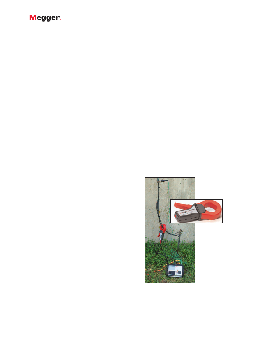
The
ART testing capability combines the advantages of
both of these technologies to produce a method that can
reliably measure an attached ground, and prove it! A
built-in clamp input, used in conjunction with the optional
ICLAMP accessory, connected below the point of
separation of the parallel test currents, measures only the
current flowing through the test ground, not that going
back through the utility. This current value is then used by
the microprocessor to calculate ground resistance, strictly
in accordance with
Fall of Potential or its derivative
procedures, supported by IEEE Standard 81 for proper
ground testing, and subject to the appropriate proofs.
The
ART method employs leads and probes just as does
any traditional tester. Ground resistance can be profiled
and graphed by moving the potential probe against the
position of the current probe, and a Fall of Potential
graph, Slope Method mathematical proof, or any of the
other proven methods utilized to demonstrate the
accuracy of the test. The only thing different from the
operation of a familiar, traditional ground tester is that the
clamp permits separation of the test currents in an
attached or otherwise parallel-grounded system. This
technique enables local grounds to be tested without
lifting the utility connection, yet with the ease, reliability
and confidence of a separate commissioning test.
Current measuring clamp (inset)
for ART testing capability