Ground resistivity measurement, Ground potential measurement, Earth measurement on pylons with earth cable – Atec AEMC-6472_6474 User Manual
Page 3: And r, Can also be measured
R
S
R
H
E
S
H
ES
1
2
3
4
C.A 6474
C.A 6472
Auxiliary
electrode
4 Ampflex channels connected
Reference
potential
Earth cable
High Voltage
Line
Current
injection
rod
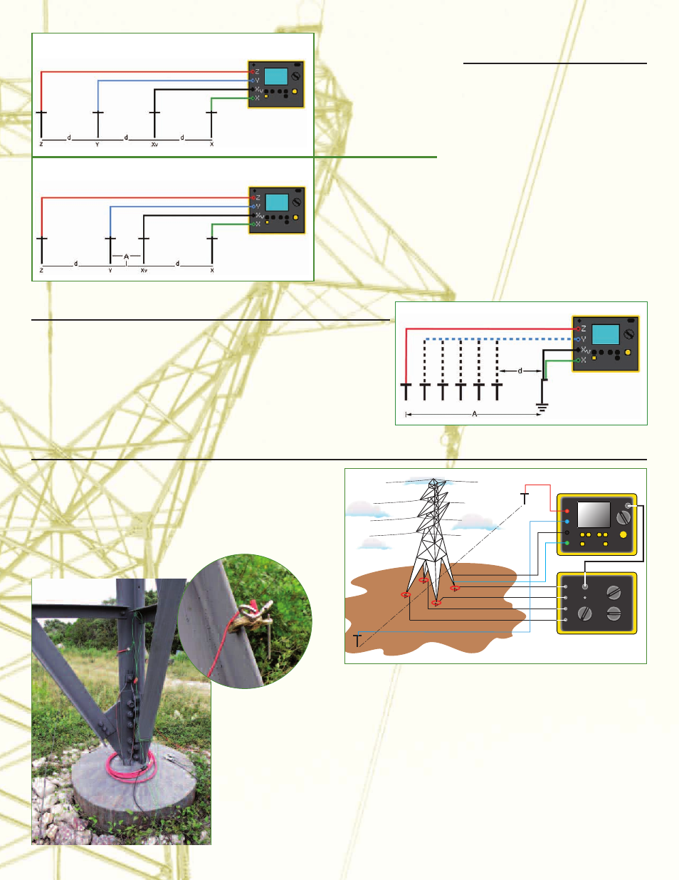
GROUND RESISTIVITY
MEASUREMENT
When it is possible to choose the
position of the earth connection,
resistivity measurement helps to assess
the ground and thus determine the place
where the earth resistance will be lowest
(optimization of construction costs).
The Model 6472 automatically calculates
the resistivity of the ground (
ρ) using the
Wenner or Schlumberger method, as
soon as the distances used between the
rods have been entered. The resistances
of the rods R
E
, R
ES
, R
S
and R
H
can also be
measured.
Wenner method:
the distances between
the 4 rods are identical:
d
ρW = 2.π.d.R
S
-
SE
Schlumberger method:
the distance between
the 2 central rods S & ES
is A
the distance between
the 2 outside rods E & H
is 2d
ρS = (π.(d
2
-A
2
/4).R
S
-
SE
) /4
GROUND POTENTIAL MEASUREMENT
This measurement can be used to determine the value of the potential as a
function of distance. By performing several measurements with different
distances (d), it is thus possible to track the change in potential around
an earthing system.
EARTH MEASUREMENT ON PYLONS WITH EARTH CABLE
High-voltage lines are usually equipped with an earth cable to
allow lightning to discharge to earth via the pylons. As all the
pylons are connected to this conductor, all the pylons' earth
resistances are in parallel. This means that it is impossible to
measure pylon resistance using traditional 3P methods unless
the earth cable is disconnected, which is a dangerous and
time-consuming operation.
Used in conjunction with the Model 6474 vectorial processing unit, the
Model 6472 offers the possibility of measuring a pylon's earth resistance even
if it is part of a parallel earth network, by selective measurement of the
pylon in question.
With 4 current sensors (Ampflex) positioned around the footings of the pylon and a
frequency scan up to 5 kHz, it is possible to measure the earth impedance of the pylon
precisely and selectively.
Furthermore, the use of flexible sensors means that this concept can be adapted
to any pylon geometry.
A single measurement is sufficient to acquire all the essential quantities:
– overall earth resistance of the line
– resistance of the pylon under consideration
– resistance of each pylon footing
– resistance of the earth cable between pylons
WENNER METHOD
SCHLUMBERGER METHOD
EARTH SYSTEM