0 indicators, controls and connectors – Alpha Technologies APU Control Module (ACM) User Manual
Page 14
018-340-B0-001 Rev. A
14
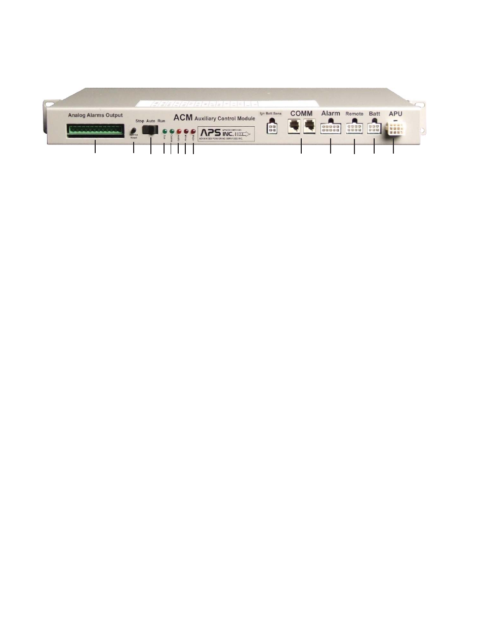
3.0 Indicators, Controls and Connectors
APU Control Module LED Indicators and switches:
1. “Major” Alarm Indicator (Red LED)
2. “Minor” Alarm Indicator (Red LED)
3. “Notify” Indicator (Amber LED)
4. “Comm” Indicator (Green LED)
5. “System” Indicator (Green LED)
6. “Run-Auto-Stop” Switch
7. “Service/Reset” Push Button Switch
8. Analog Alarms Output
9. Communications Interface
10. Alarm: Input Signals
11. Remote: DCIU Breaker Trip
12. Battery DC Bus Input
13. APU AC/DC Power and Control Signals
The ACM user interface consists of 5 LEDs (1-5), a three-position rocker switch (6), and
a momentary contact, push-button switch (7). The Communications Interface (9) can
be used to attach an Alpha Technologies system controller. Provisions are made for
Transponder connections through the Analog Alarms Output (8). The interface with the
DOCSIS transponder platform is with an offset data cable from one of the parallel connected
communications ports (9).
Fig. 3-1, ACM Front Panel
1
2
4 3
5
6
7
8
9
10
11
12
13
- AlphaCell GelCell Series (32 pages)
- FXM 650, 1100, 2000 UPS (96 pages)
- Cordex 48-1.2kW (68 pages)
- Radium MiniBay (57 pages)
- Fiber Backhaul Enclosure (FBE) (19 pages)
- FBE2322 Enclosure System (38 pages)
- FlexNet PMR, GMR Series (49 pages)
- Te25xh (38 pages)
- FlexNet MPS48-12M - Technical Manual (33 pages)
- FlexNet MPS48-12M - Quick Start Guide (2 pages)
- FlexNet ELPM 300-48D (25 pages)
- FlexNet FMPS (40 pages)
- FlexPoint AX Series (34 pages)
- FlexPoint FPR1207-F - Technical Manual (18 pages)
- FlexPoint FPR1207-F - Quick Start Guide (2 pages)
- AlphaGen PN-6x-T 7.5kW 48VDC - Installation and Operation Manual (79 pages)
- AlphaGen CE-3x2 5K-T 48Vdc (95 pages)
- AlphaGen PN-6x-T 7.5kW 48Vdc (95 pages)
- AlphaGen 3.5_5.0kW Kohler COM5 (80 pages)
- Security Bar Field For UPE-3, UPE-6, UPE-M3, UPE-M6, PN Series and CE Series (2 pages)
- AMPS80 HP (116 pages)
- 255A Bypass Switch (24 pages)
- AMP24 HP (108 pages)
- FXM350_Micro350 UPS (112 pages)
- CFR 600, CFR 600XT, CFR 1000 (70 pages)
- BPS Series Bypass Switch (36 pages)
- CFR Intelligent Interface Device (54 pages)
- CFR Redundant Control Unit (23 pages)
- CFR 5000, CFR 5000RM (88 pages)
- CFR 3000, CFR 3000RM (86 pages)
- CFR 1500, CFR 1500RM (83 pages)
- CFR 1500, CFR 2000, CFR 2500, CFR 3000 (76 pages)
- Continuity: 1000_2000_3000 (48 pages)
- Continuity Battery Pack (20 pages)
- Continuity: 6K_10K (52 pages)
- Micro, Micro XL, Micro XL3 UPS (99 pages)
- Micro Secure UPS (80 pages)
- Te17 (32 pages)
- Te45 (68 pages)
- Te41, 48V (76 pages)
- Te41, 24V (72 pages)
- Te43 (60 pages)
- AlphaGuard AG-CMT Installation (2 pages)
- AlphaGuard AG-CMT-3SC_4SC-P (2 pages)
- Digital Midtron DM-3200 AT (2 pages)