Alpha Technologies Battery Enclosure (BE) User Manual
Page 10
ALPHA
TECHNOLOGIES
DOCUMENT NO.
033-074-C0-001
Revision
10
A
Page
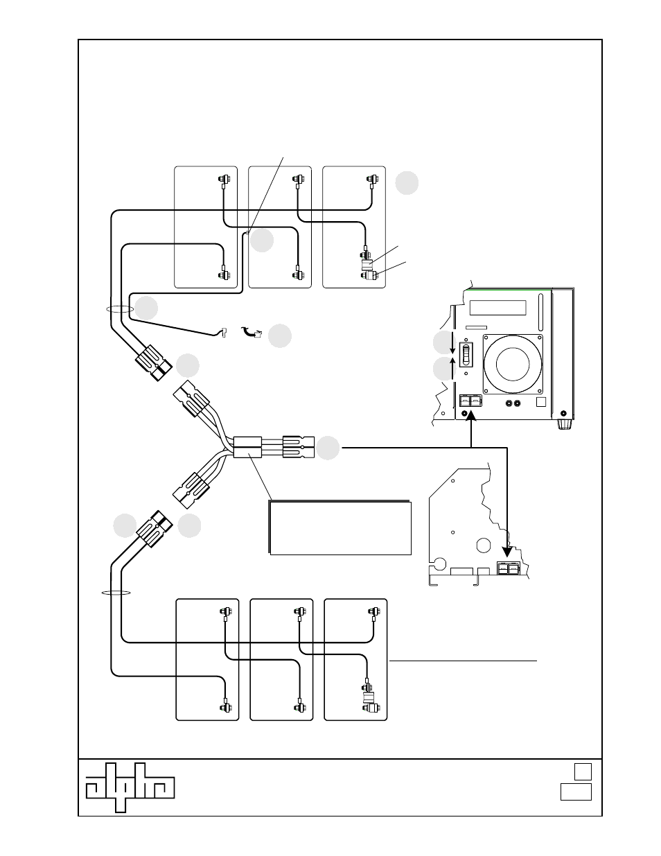
Battery Enclosure (BE) installation
procedure on UPE Enclosure
Step
12
Step
10
Step
11
Step
12
Step
9
Step
7
Step
6
Step
5
Step
8
Step
13
or
R.T.S connector to logic card
or input jack module
(dependant upon model options)
BLK -
RED +
BLK -
BLK -
BLK -
BLK -
RED +
RED +
RED +
RED +
XMS2 battery connections
XM battery connections
“Y”-adapter
(p/n 874-655-20)
Allows the connection of two parallel
battery strings to one XM or XMS2 power
supply.
Wires pass through hole in Battery
Enclosure
Wires pass through hole in shelf.
Temperature Sensor
(moved from lower battery shelf to corresponding position in upper battery shelf)
-
-
-
+
+
+
-
-
-
+
+
+
Long Black wire
Long Black wire
Long Red wire
Long Red wire
Fuse
Spacer
Newly-installed batteries in upper
Battery Enclosure (BE)
Existing batteries in UPE enclosure
- AlphaCell GelCell Series (32 pages)
- FXM 650, 1100, 2000 UPS (96 pages)
- Cordex 48-1.2kW (68 pages)
- Radium MiniBay (57 pages)
- Fiber Backhaul Enclosure (FBE) (19 pages)
- FBE2322 Enclosure System (38 pages)
- FlexNet PMR, GMR Series (49 pages)
- Te25xh (38 pages)
- FlexNet MPS48-12M - Technical Manual (33 pages)
- FlexNet MPS48-12M - Quick Start Guide (2 pages)
- FlexNet ELPM 300-48D (25 pages)
- FlexNet FMPS (40 pages)
- FlexPoint AX Series (34 pages)
- FlexPoint FPR1207-F - Technical Manual (18 pages)
- FlexPoint FPR1207-F - Quick Start Guide (2 pages)
- AlphaGen PN-6x-T 7.5kW 48VDC - Installation and Operation Manual (79 pages)
- AlphaGen CE-3x2 5K-T 48Vdc (95 pages)
- AlphaGen PN-6x-T 7.5kW 48Vdc (95 pages)
- AlphaGen 3.5_5.0kW Kohler COM5 (80 pages)
- Security Bar Field For UPE-3, UPE-6, UPE-M3, UPE-M6, PN Series and CE Series (2 pages)
- AMPS80 HP (116 pages)
- 255A Bypass Switch (24 pages)
- AMP24 HP (108 pages)
- FXM350_Micro350 UPS (112 pages)
- CFR 600, CFR 600XT, CFR 1000 (70 pages)
- BPS Series Bypass Switch (36 pages)
- CFR Intelligent Interface Device (54 pages)
- CFR Redundant Control Unit (23 pages)
- CFR 5000, CFR 5000RM (88 pages)
- CFR 3000, CFR 3000RM (86 pages)
- CFR 1500, CFR 1500RM (83 pages)
- CFR 1500, CFR 2000, CFR 2500, CFR 3000 (76 pages)
- Continuity: 1000_2000_3000 (48 pages)
- Continuity Battery Pack (20 pages)
- Continuity: 6K_10K (52 pages)
- Micro, Micro XL, Micro XL3 UPS (99 pages)
- Micro Secure UPS (80 pages)
- Te17 (32 pages)
- Te45 (68 pages)
- Te41, 48V (76 pages)
- Te41, 24V (72 pages)
- Te43 (60 pages)
- AlphaGuard AG-CMT Installation (2 pages)
- AlphaGuard AG-CMT-3SC_4SC-P (2 pages)
- Digital Midtron DM-3200 AT (2 pages)