Installation fig. 2 pad layout – Alpha Technologies CESC User Manual
Page 10
5.5
9.2
3.5
3.5
22.0
CESC
Generator
or PN3/4
10.25
6.8
All Measurments
in Inches
19.5
14.7
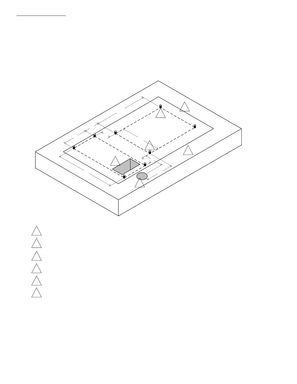
Pads can either be poured on site, or precast by Alpha Technologies. The mounting holes on
the bottom of the high security PN-3 will fit both a standard PN-3 pad, and a CE3X pad.
Precast pad model number PCC-SC-3X, Alpha P/N 641-061-10 or PCD-SC-3X, Alpha P/N
641-064-10 (east coast) are available for this system.
All measurements are indexed to the front left generator mounting stud.
Indicates outline of enclosure.
Alpha standard; recommended distance (6" minimum) between edge of pad and cabinet.
Four inch diameter hole for AC power IN (non-metered installation).
All mounting hardware must be stainless, galvanized, or better to prevent corrosion.
5" x 8" rectangular cutout for all internal connections including: generator power and/or coax
cable conduit sweeps. Position between mounting studs not critical.
A 25+ year continuous vapor barrier must be used between the enclosure and the pad to
prevent moisture ingress and possible corrosion caused by metal to concrete contact.
The vapor barrier material (such as 30 lb felt, neoprene pond liner, or heavy grade tar
paper) must be initially extended at least 6" in all directions around the perimeter of the
enclosure. After the enclosure is secured to the pad, the material can be cut closer to
the enclosure, using the appropriate knife or cutting tool.
5
6
1
2
3
4
2.1
Concrete Pad Preparation
1
2
3
4
5
6
10
031-106-C1-001 Rev. A
2. Installation
Fig. 2 Pad Layout