3 sample input power panels, Primary service – Alpha Technologies PN-4 User Manual
Page 18
031-103-B0-004, Rev. D
18
4.0 Installation,
continued
4.1
Utility Powering, continued
4.1.3 Sample Input Power Panels
For more information on available models of the Input Power Panel, refer to Section
5.0, PN Series Options.
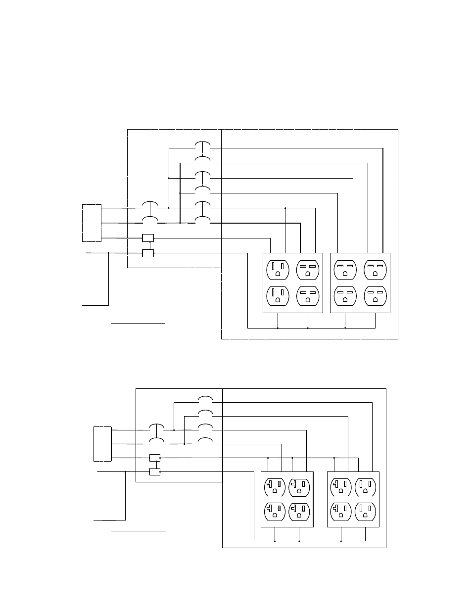
Fig. 4-3, Schematic: Primary Service BBX-100A-8POS with IPP-240-3
Fig. 4-4, Schematic: Primary Service BBX-100A-8POS with IPP-120-3
IP P -120-3
120V /20A 120V /20A
120V /20A
G F C I
Neutral
L ine 1
L ine 2
15A
20A
20A
50A
20A
F rom
S ervic e
S upply
Main B onding
J umper
G
N
Load
Service
and
Distribution
Grounding
Electrode
Conductor
Lightning
Protection
Service
and
Distribution
Service
Main
Load
BBX-100A-8POS
Grounding
Electrode
Conductor
Lightning
Protection
Primary Service
1) Main bonding jumper is installed.
2) Grounding electrode conductor is installed.
3) Lightning protection is bonded outside of cabinet.
Primary Service
1) Main bonding jumper is installed.
2) Grounding electrode conductor is installed.
3) Lightning protection is bonded outside of cabinet.
240/15A
Neutral
S ervic e
Main
L ine 1
L ine 2
15A
15A
15A
50A
B B X -100A-8PO S
IP P -240
-
3
240V /15A
240V /15A
120V /15A
G F C I
240V /15A
Main B onding
J umper
G
N
From
Service
Supply