Alpha Technologies PN-4 User Manual
Page 16
031-103-B0-004, Rev. D
16
1
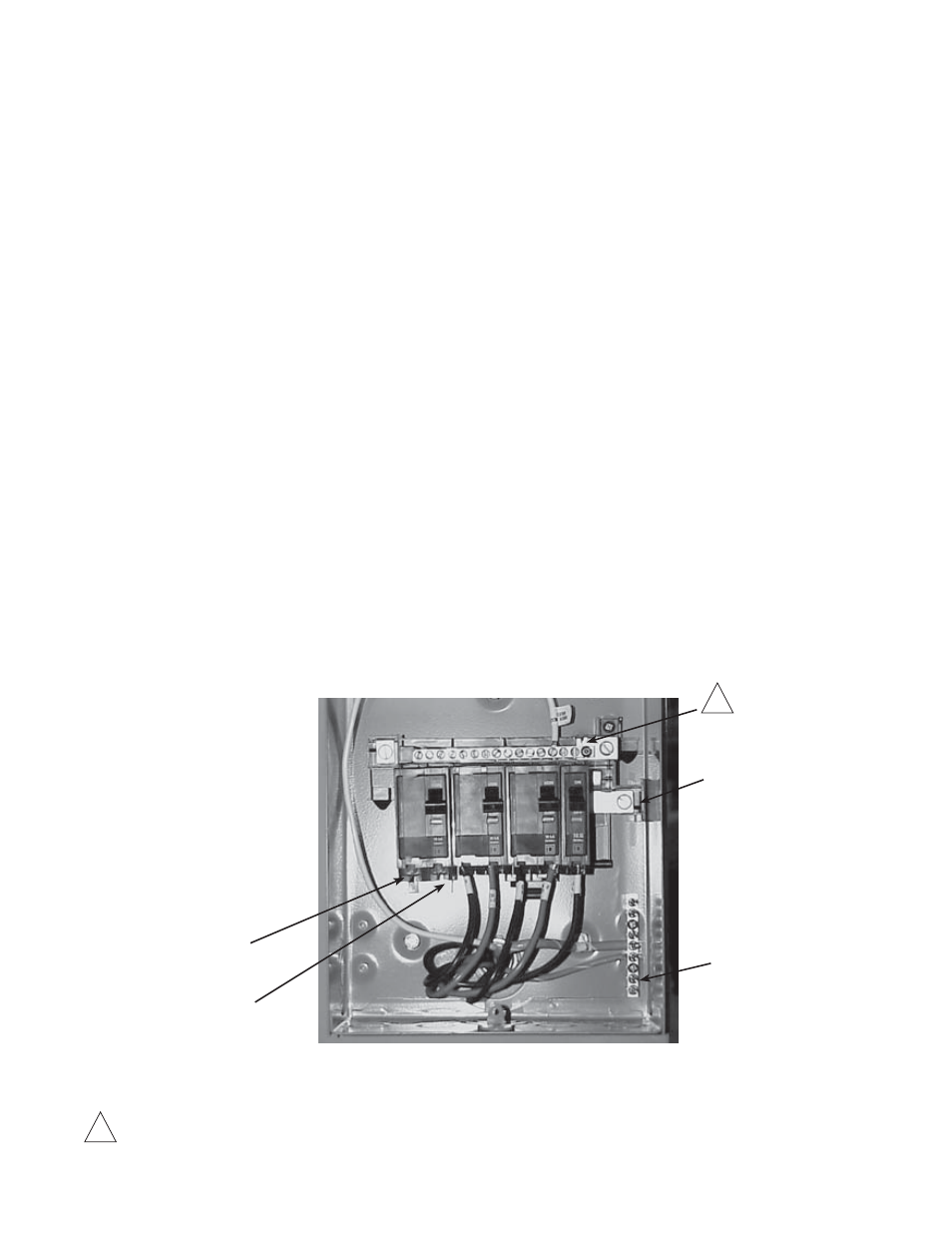
Bond made by bonding screw only if no other service panel is used (must be installed on site only if
primary service entrance).
4.0 Installation,
continued
4.1
Utility Powering, continued
4.1.1 Connection Procedure for the BBX-100A-8POS Service Disconnect:
1. Locate the service entrance panel on the enclosure (exterior). Remove the cover
to access the circuit breaker assembly. If this service panel is to be used as the
primary service entrance, neutral must be bonded to ground by installing the
green bonding screw (provided) in the hole in the neutral bus.
2. Remove the knockout located at the base of the service entrance to accept the
conduit.
3. Install the conduit nipple into the service entrance via the knockout and secure
with the appropriate threaded conduit locknut.
4. Locate the two screw terminals (L1 and L2) on the bottom of the input circuit
breaker.
5. Connect one of the incoming black #6 AWG wires to L1 (left terminal). Connect
the remaining black (or red) #6 AWG wire to L2 (right terminal). Note: if the wire
at L2 is black, mark it with red tape (or label).
6. Connect the white #6AWG wire to the neutral (N) bus lug, located to the top right
of the circuit breaker assembly.
7. Connect the #6AWG bare solid or stranded wire for the Grounding Electrode
Conductor (earth ground) to the ground and neutral bus located to the right side
of the circuit breaker assembly.
8. Notify the electrical inspector to approve the service entrance wiring. Once
approved, contact the local power utility for electrical service.
Neutral (N) Bus Lug
Line 2
Line 1
Grounding Electrode
Conductor
1
Fig. 4-1, BBX-100A-8POS Service Disconnect