0 overview to the field installation instructions, 0 communications card settings – Alpha Technologies XP-EDH4 - Installation User Manual
Page 3
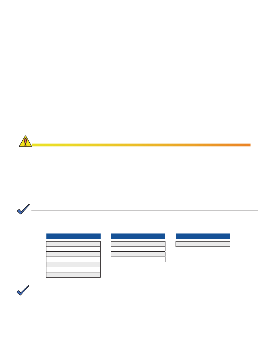
Verify the switches and jumpers on the respective communications cards are set as indicated in the tables below.
XM - USM
P1 = 2 & 3
P2, P4, P5, P6 = Closed
P3 = Open
P7 = 5V
P8, P9, P13 = 1 & 2
P14 = N/A
SW4 = 0
Output Current switch settings are determined by the output current capability of the power supply and must be
configured accordingly. Refer to your power supply user manual for setting details.
Typical I
out
settings for the following communications cards:
USM:
N/A
•
USM2: SW1-3 = Output #1, SW1-4 = Output #2
•
USM2.5: SW1-3 = Output Current Scaling, 15A or 22A
•
RPM:
No switch setting required
•
XM2 - USM2
SW1-1, 2, 6, 8 = On
SW2-1, 3, 4 = On
JP1 = C & 1
JP2 = 1 & 2
1.0
Overview to the Field Installation Instructions
2.0 Communications Card settings
XM2 - USM2.5
SW1-1, 2, 6 = On
Table 1, XM-USM switch settings
Table 2, XM2-USM2 switch settings
Table 3, XM2-USM2.5 switch settings
745-419-C4-001 Rev. A (09/2009)
3
The EDH4 transponder provides the ability to manage network power through an existing cable modem infrastructure,
for a variety of power supplies as shown in this document.
The steps comprising the installation procedure are as follows:
1. Setting the jumpers and switches in their respective communications cards [Section 2.0]
2. Connecting the transponder to its respective power supply and system equipment [Section 3.0]
3. Verifying Installation and network connectivity [Section 4.0]
Save these instructions for future reference.
Installation Notes:
Before field installation, the transponder's MAC address should be loaded into the CMTS, and DOCSIS
•
configuration file options should be set.
Use a surge protector in the cabinet when the transformer is used to measure line voltage.
•
Do not place the transponder on top of the power supply or batteries.
•
Make all battery harness connections and connect the interface cable to the power supply before connecting the
•
cables to the transponder.
Alpha AM power supplies with RPM interface cards marked 700-019-28, 700-019-31 and 700-019-40 are
compatible with the DOCSIS HMS Analog Transponder.
NOTE:
NOTE:
When the EDH4 replaces an existing EDH2 or EDH3 Transponder, do not plug the AUX PWR cable into the
connector labeled CNTL. Although these connectors are identical in shape, the functionality between them is
different. The CNTL connection provides power for the Battery heater mat. System damage will occur if the
AUX PWR cable is plugged into the CNTL connector. Contact Alpha Technologies regarding the disposition of
the existing AUX PWR cable.
CAUTION!