Alpha xm, xm2 and am models, Power supply communications card settings, Overview to the field installation instructions – Alpha Technologies XP-EDH3 User Manual
Page 2
Before field installation, the transponder's MAC address should be loaded into the CMTS, and DOCSIS configuration file
options should be set.
Alpha XM, XM2 and AM Models
See Subsequent Sections for power supply-specific setup instructions
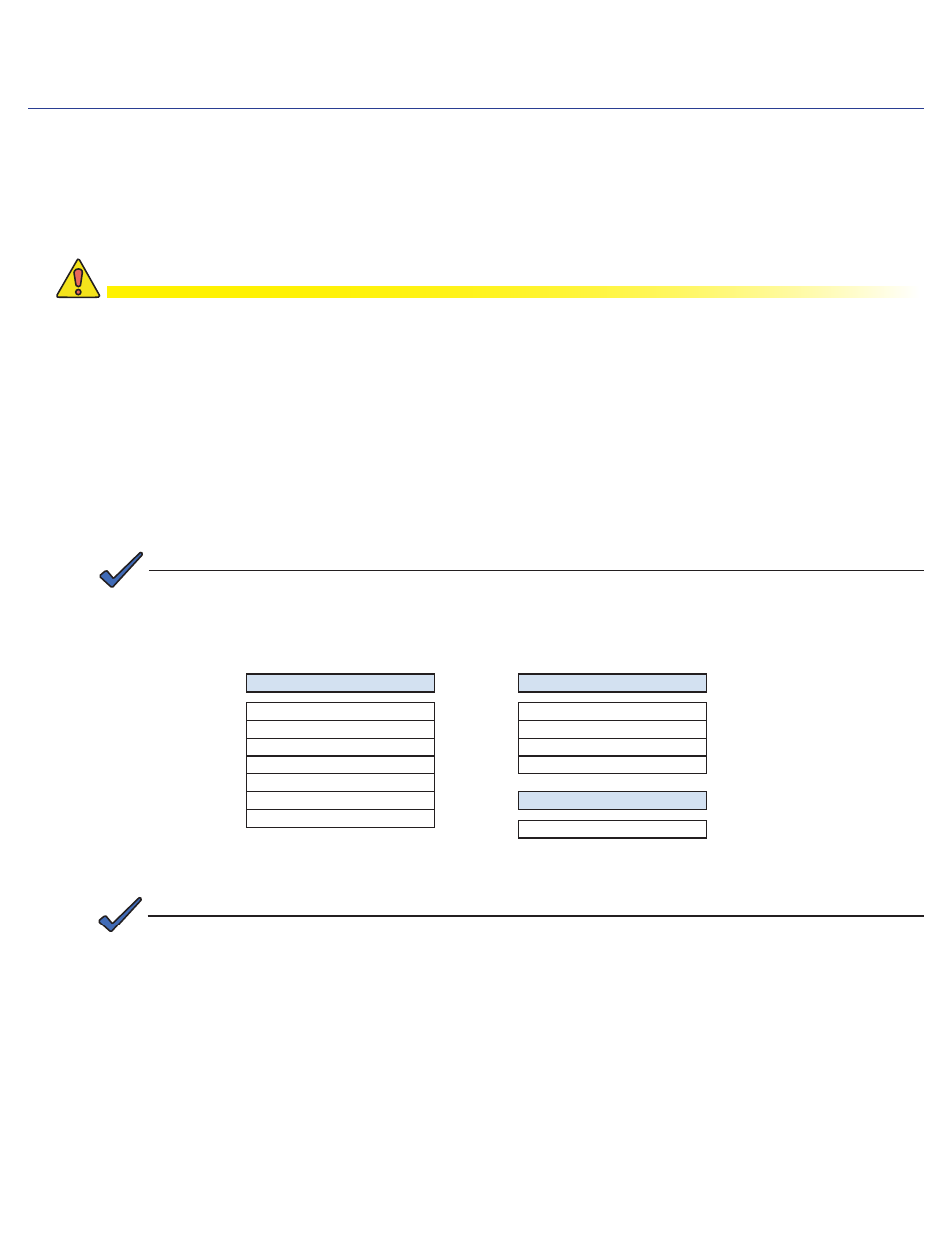
Power Supply Communications Card Settings
XM - USM
P1 = 2 & 3
P2, P4, P5, P6 = Closed
P3 = Open
P7 = 5V
P8, P9, P13 = 1 & 2
P14 = N/A
SW4 = 0
Output Current switch settings are determined by the output current capability of the power supply and should be
setup accordingly. See your power supply user manual for setting details.
USM:
N/A
•
USM2:
SW1-3 = Output #1, SW1-4 = Output #2
•
USM2.5:
SW1-3 = Output Current Scaling, 15A or 22A
•
RPM :
No switch setting required
•
XM2 - USM2
SW1-1, 2, 6, 8 = On
SW2-1, 3, 4 = On
JP1 = C & 1
JP2 = 1 & 2
XM2 - USM2.5
SW1-1, 2, 6 = On
Overview to the field installation instructions
CAUTION!
Use a surge protector in the cabinet when the transformer is used to measure line voltage.
Do not place the transponder on top of the power supply or batteries.
Make all battery harness connections and connect the interface cable to the power supply before
connecting the cables to the transponder.
745-419-C3-001 Rev. A (02/2009)
2
The XP-EDH3 transponder provides the ability to manage network power through an existing cable modem
infrastructure, for a variety of power supplies as shown in this document.
These instructions provide information important to the successful installation, connection and operational verification of
the Alpha XP-EDH3 transponder in a variety of systems.
Save these instructons for future reference.
Alpha AM power supplies with RPM interface cards marked 700-019-28, 700-019-31 and 700-019-40 are
compatible with the DOCSIS HMS Analog Transponder.
NOTE:
NOTE: