Configuration, Continued – Alpha Technologies USM2.5 Status Monitor User Manual
Page 13
3. Configuration
704-683-B0-004, Rev. D
13
3.2 USM2.5 Configuration,
continued
Always verify USM2.5 configuration especially after upgrading or modifying the XM Series 2
Power Supply.
Function Switch SW1 Reference
The following information describes each switch position (1–8) for the DIP switch SW1. SW1
is an eight switch component used primarily to select analog scaling and digital signal
polarity for the USM2.5 card.
SW1 (1 and 2): Inverter Battery Voltage Scaling Select
SW1, positions 1 and 2 are used together to select the appropriate scaling for the XM
Series 2 battery voltage measurement, measured at J4 pin 5.
SW1 (1)SW1 (2)Battery Scaling
OFF
OFF
0.1VDC/VDC
OFF
ON
0.3VDC/VDC
ON
OFF
0.3VDC/VDC Same as previous setting.
ON
ON
0.5VDC/VDC
SW1 (3): Output Current Scaling
SW1, position 3 is used to select the appropriate scaling for the XM Series 2 AC OUTPUT
CURRENT#1, measured at J4 pin 8 and AC OUTPUT CURRENT #2 pin 13.
SW1 (3)Output Current #1, #2
OFF
0.4VDC/AAC for Power Supply Output Current rating less than 20A.
ON
0.4VDC/AAC for Power Supply Output Current rating equal to or greater than 20A.
NOTE: Switch 1-3 should always be ON for units equipped with the ONU option.
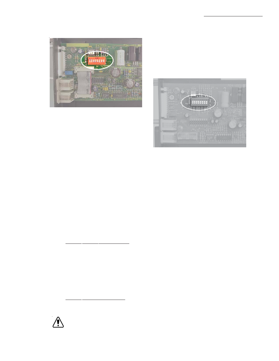
Figure 3-1; USM2.5 Switch Location
(Old Version )
Figure 3-2; USM2.5 Switch Location
(New Version )