Alpha Technologies DOCSIS HMS User Manual
Page 14
14
745-420-C0-002 Rev. B
2.0
Transponder Installation, continued
2.3
Installing the Transponder Hardware, continued
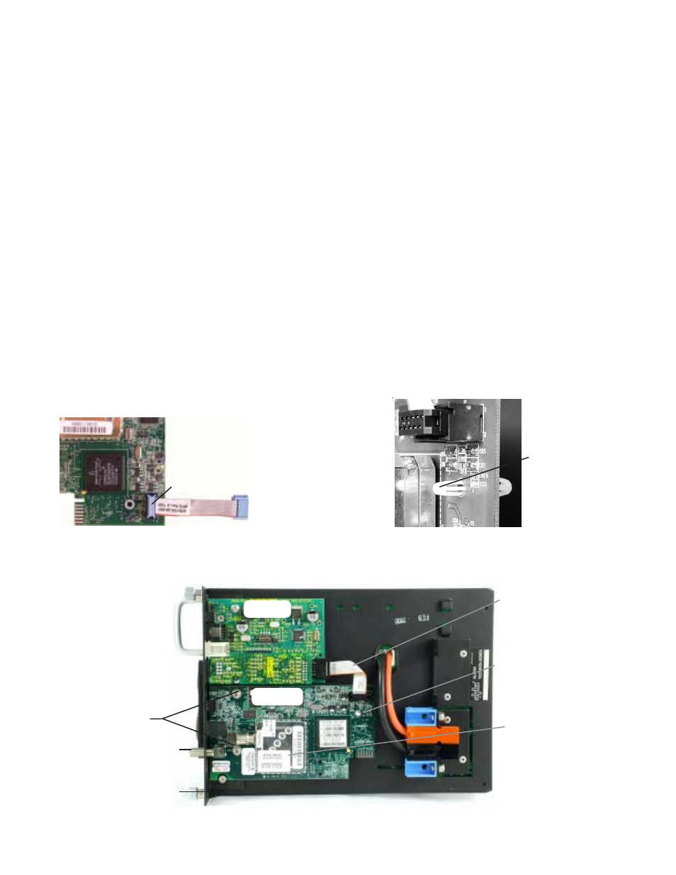
4.
Attach the new transponder ribbon cable supplied to the 10-pin connector on the
transponder as shown in Fig. 2-1. The connectors are keyed to prevent incorrect
orientation.
5.
Attach the plastic standoff to the transponder PC board as shown in Fig 2-2.
6.
Verify that the MAC address label is installed on the transponder. If the label is missing,
locate the label in the packaging and apply to the transponder as shown in Fig 2-3.
7.
Place the transponder as shown in Fig 2-3 below. The RF connector must be inserted
through the front of the Comm Module bracket.
8.
Press the standoff into the Inverter Module chassis.
9.
Secure the transponder to the Comm Module Bracket with the two screws provided.
10. Connect the transponder ribbon cable to the EDSM. Note the 90
o
twist in the cable.
11. Reconnect the Inverter Module ribbon cable, and reinstall the Inverter Module into the power
supply.
12. Reconnect all the cables unplugged in Step 2 .
13. Move the Battery Breaker to the ON position.
PCB Standoff
10-pin Connector
Fig. 2-1, Attaching the10-pin Connector
Fig. 2-2, Attaching the PCB Standoff
Fig. 2-3, Transponder Components
Securing Screws
MAC Address Label
Ribbon Cable
PCB Standoff
RF Connector
Comm Module Bracket
EDSM
DOCSIS