Programming the digital input – Alpha Technologies Cordex Controller Panel Mount_Rack Mount 125_220Vdc User Manual
Page 19
Argus Technologies Ltd.
018-570-C0 Rev B WC
Printed in Canada. © 2005 Argus Technologies Ltd. ARGUS and CORDEX are trademarks of Argus Technologies Ltd. All Rights Reserved.
Page 9 of 14
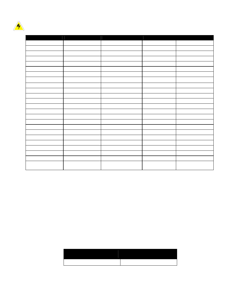
CAUTION: to reduce risk of fire, use only 0.129mm2 (#26 AWG) or larger wire.
Terminal
Description
Default Name
Signal
Range
1 and 2; V2
Voltage Input 2
Charge Voltage
Pos (+)/Neg (-)
0-300Vdc
3 and 4; GP1*
General Input 1
GP1
Pos (+)/Neg (-)
0-300Vdc
5 and 6; GP2*
General Input 2
GP2
Pos (+)/Neg (-)
0-300Vdc
7 and 8; GP3*
General Input 3
GP3
Pos (+)/Neg (-)
0-300Vdc
9 and 10; GP4*
General Input 4
GP4
Pos (+)/Neg (-)
0-300Vdc
11 and 12; T1
Temp Input 1
T1
Pos (+)/Neg (-)
0-20Vdc
13 and 14; T2
Temp Input 2
T2
Pos (+)/Neg (-)
0-20Vdc
15 and 16; I2
Current Input 2
I2
Pos (+)/Neg (-)
±50mV
19 and 20; D1**
Digital Input 1
Distribution Fuse (Alarm)
N/A
Short or open
21 and 22; D2**
Digital Input 2
Distribution CB (Alarm)
N/A
Short or open
23 and 24; D3**
Digital Input 3
Battery CB (Alarm)
N/A
Short or open
25 and 26; D4**
Digital Input 4
Battery CB (Alarm)
N/A
Short or open
27, 28 and 29; K1***
Alarm Output 1 LVD1
NC/COM/NO 220Vdc,
0.4A
30, 31 and 32; K2***
Alarm Output 2 LVD2
NC/COM/NO 220Vdc,
0.4A
33, 34 and 35; K3***
Alarm Output 3 LVD3
NC/COM/NO 220Vdc,
0.4A
36, 37 and 38; K4***
Alarm Output 4
System Minor
NC/COM/NO
220Vdc, 0.4A
39, 40 and 41; K5***
Alarm Output 5
System Major
NC/COM/NO
220Vdc, 0.4A
42, 43 and 44; K6***
Alarm Output 6
AC Mains Hi-Low
NC/COM/NO
220Vdc, 0.4A
45, 46 and 47; K7***
Alarm Output 7
Not assigned
NC/COM/NO
220Vdc, 0.4A
48, 49 and 50; K8***
Alarm Output 8
Not assigned
NC/COM/NO
220Vdc, 0.4A
51, 52 and 53; K0****
Alarm Output 0
System Fail Output
NC/COM/NO 220Vdc,
0.4A
54 and 55; B PWR
Secondary Power
Secondary Power
Pos (+)/Neg (-)
90-300Vdc
56 and 57; A PWR
Power
Power
Pos (+)/Neg (-)
90-300Vdc
DCCT input; P3
Current Input 1
I1
Pos (+)/Neg (-);
Pwr (+)/Pwr (-)
±15Vdc, 100mA max.
Table A–Wiring connections
*
Bipolar (Voltage Input) is ±150Vdc, Unipolar Voltage (Input) is 0—300Vdc, Temp Probe is 0—20Vdc with power source.
**
See Table B for definitions of impedance levels.
***
Can be configured to de-energize on alarm (DOA) or energize on alarm (EOA).
****
System Fail output relay is fail-safe and will de-energize during an alarm condition.
NOTE: DCCT power output is protected against short circuits and is able to power four DCCTs.
To aid the user with installation, frequent reference is made to drawings located at the rear of this manual.
Custom configurations may be detailed within the Argus power system documentation package.
5.7.1
Programming the Digital Input
The digital input channels (terminals 19 through 26) can be programmed for “active high” or “active low.” Active
high indicates “alarm on the presence of a short circuit” and active low indicates “alarm on the removal of the
short circuit.”
NOTE: See CXC Software manual for detailed instruction on programming.
Impedance Level (Ohms)
Considered As “0” (Off)
Impedance Level (Ohms)
Considered As “1” (On)
> 1M
< 1
Table B–Digital input impedance level definitions