Analog inputs, Voltage input 2 (v2), Midpoint monitoring (connection example) – Alpha Technologies Cordex Controller Panel Mount_Rack Mount 125_220Vdc User Manual
Page 18: Digital inputs
Argus Technologies Ltd.
018-570-C0 Rev B WC
Printed in Canada. © 2005 Argus Technologies Ltd. ARGUS and CORDEX are trademarks of Argus Technologies Ltd. All Rights Reserved.
Page 8 of 14
5.6 Analog
Inputs
WARNING
Ensure the correct polarity is used for all input cable terminations.
The analog input channels are used to monitor various types of electrical signals. Some of the analog channels
are reserved for specific signals, while others are designated as general-purpose inputs, which accommodate
various types of analog signals.
Bundle the input cables together and route through the entry holes.
NOTE: Default configurations and terminal numbers described below have been summarized in Table A (next page).
Refer also to foldout drawings located at the rear of this manual. Custom configurations may be detailed within
the Argus power system documentation package.
5.6.1
Voltage Input 2 (V2)
CAUTION
If the V2 sense leads are disconnected from the CXC, the following will occur:
• The CXC registers the absence of DC as an invalid condition.
• The LVD will not be de-activated.
• The rectifier voltage may increase slightly, typically 1.8V (5.5V maximum).
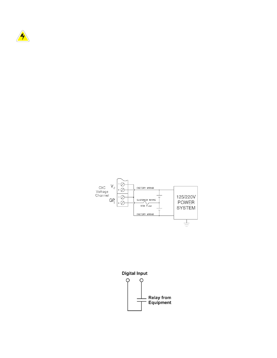
5.6.2
Midpoint Monitoring (connection example)
An analog signal configured (at the factory) for voltage can be used for mid-point monitoring. Channel V1 is used
in the example below but any of the available voltage channels can be used.
NOTE: See CXC Software manual for detailed instruction on programming.
Connect as shown ensuring correct polarity:
Figure 4–Connection example for mid-point monitoring
5.7 Digital
Inputs
The digital input channels are used to monitor various alarm and control signals. Shorting an input with a voltage-
free relay contact will activate the channel.
Figure 5–Showing connection method