Aeromotive 18688 - PHANTOM 340 STEALTH FUEL SYSTEM User Manual
Page 9
39. Prep the new tank by making all the necessary connection (feed, return, vent and electrical) before placing tank in
vehicle. In most cases, once the tank is placed in the vehicle these connection will not be accessible. For electrical
wiring refer to Figure 2-1.
Note: Tank vent must be at least 6” above the top of the tank if a roll-over valve is used (highly
recommended).
40. Reinstall the fuel tank in the vehicle. In some cases it may be necessary to space the fuel tank down to allow
additional clearance for the new pump outlet, top plate and fittings. 1/2" thick foam material is provided and should
be divided and installed at the top of the tank on either side, between the tank and the trunk floor,to help space the
fuel tank down if necessary. Additional fabrication may be necessary to gain clearance in extreme cases.
41. Now route the feed and return line under the vehicle and secure them to the chassis. It’s recommended to install a
post-filter between the fuel pump and the engine (see Aeromotive part # 12301/12321). Place the filter in a location
that is clear of suspension and exhaust system components and easy to get to for servicing.
Note: Be sure to route all fuel lines clear of any moving suspension or drivetrain components, and any
exhaust components! Protect fuel lines from abrasion and road obstructions or debris.
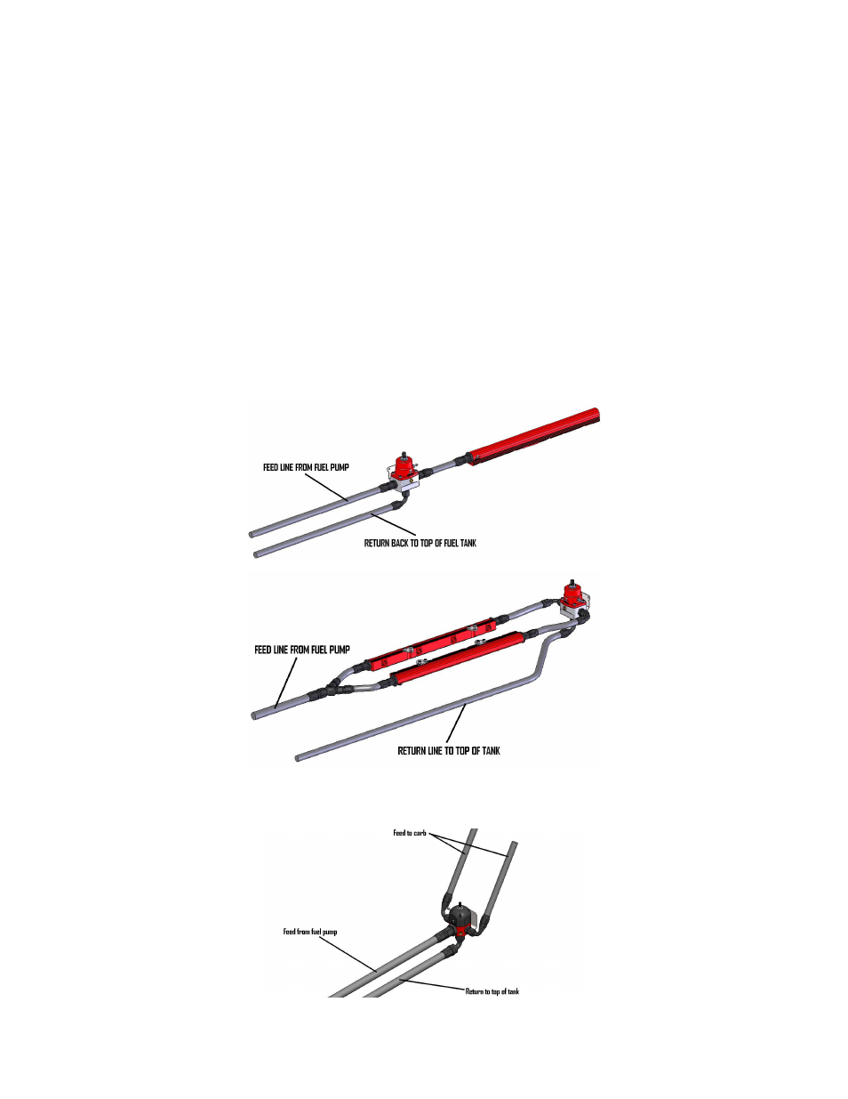
42. The pictures below are typical regulator installations for EFI setups with Aeromotive Bypass Regulator P/N 13109.
Figures 1-1 & 1-2
Fuel Rail with single inlet (Figure 1-1)
Fuel Rails with inlet/outlets (Figure 1-2)
43. Use the figure below for a single carb installation with Aeromotive Bypass Regulator P/N 13204. (Figure 1-3)
Single carb setup (Figure 1-3)