Aeromotive 17130 - 86-98.5 A1000 5.0L MUSTANG STEALTH FUEL SYSTEM User Manual
Page 9
Section 3 – Fuel Regulator Installation and Fuel Line Plumbing
3-1. In the vehicle’s engine compartment, mount the supplied fuel pressure regulator in the location established in step 1-
26. Using the supplied mounting bracket as a template, mark the bracket mounting holes and drill to accept a #10
screw.
3-2. Reattach the mounting bracket to the regulator and mount the regulator to the vehicle using two #10 screws, nuts and
lock washers (not included).
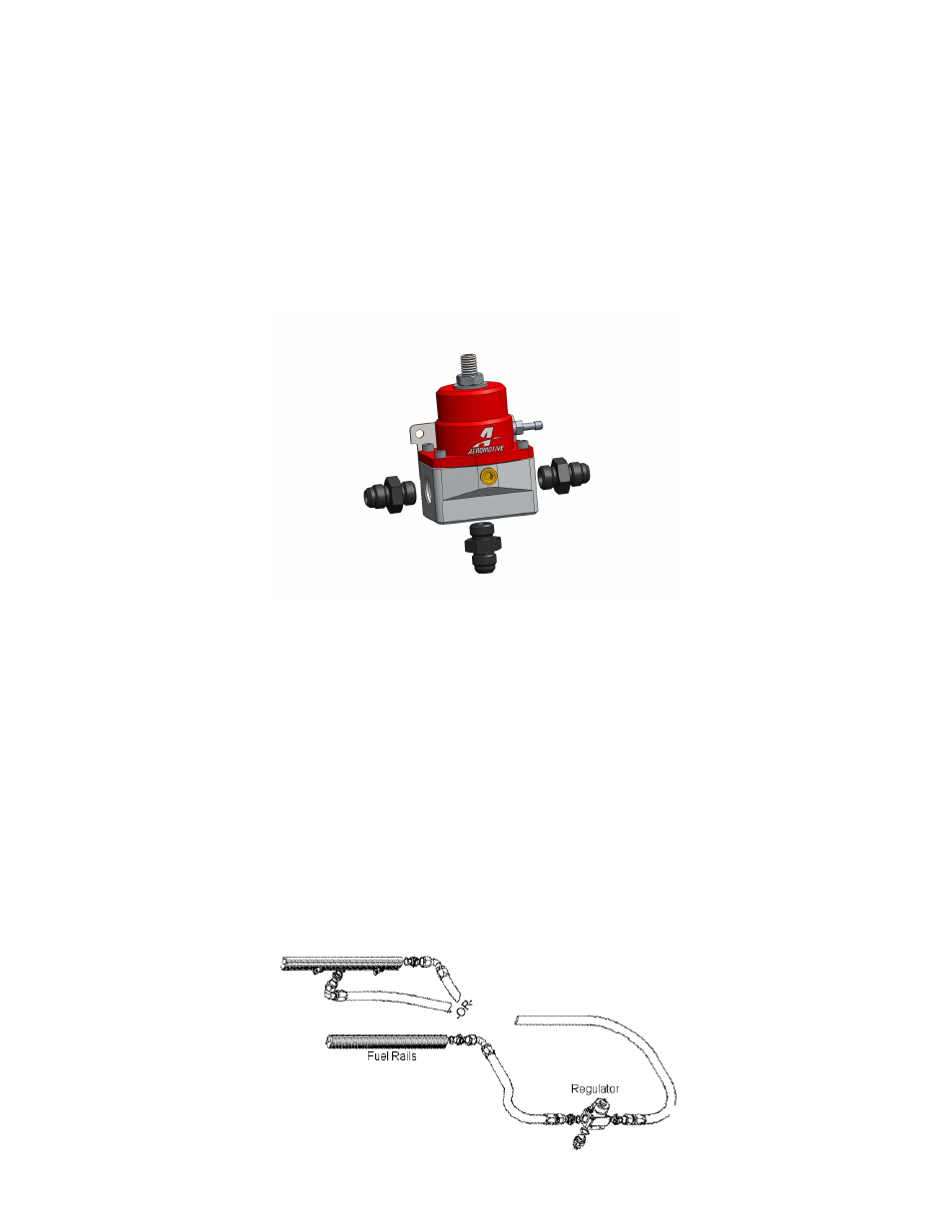
3-3. Install one of the supplied AN-06 o-rings onto the ORB (cut-off) side of all three of the ORB-06 to AN-06 male flare
fittings, if not already installed. Install one of these fittings into each of the ORB-06 inlet (side) ports located on either
side of the supplied fuel pressure regulator. Install the remaining ORB-06 to AN-06 male flare fitting into the bottom,
return port of the supplied fuel pressure regulator. See FIGURE 3-1
FIGURE 3-1
3-4. Install one of the supplied ORB-08 o-rings on the port (cutoff) side of each of four ORB-08 to AN-06 male flare fittings,
if not already installed.
3-5. Install one of these ORB-08 to AN-06 male flare fittings on the back side (firewall end) of each fuel rail and one on the
front side of the passenger side fuel rail. If there is adequate clearance between the distributor and the fuel rail on the
driver’s side rail, install the second fitting on the front side as well, if not, install the second fitting in the ORB-08 port
located on the bottom center of the fuel rail.
3-6. Starting from the fuel rails, plan a route to run an AN-06 supply line from each fuel rail to each side of the regulator,
see FIGURE 3-2. Cut the two supply lines to the determined length and install the AN-06 hose ends, as detailed in
Section 4.
Note: Be sure to route all fuel lines clear of any moving suspension or drivetrain components and any exhaust
components! Protect fuel lines from abrasion and road obstructions or debris.
3-7. Using the above steel braided hose assemblies, connect one end to the side of the fuel pressure regulator and the
other end to the fuel rails, as shown in FIGURE 3-2, and tighten.
Figure 3-2