Aeromotive 17130 - 86-98.5 A1000 5.0L MUSTANG STEALTH FUEL SYSTEM User Manual
Page 5
1-9. Now the fuel tank is ready for your Aeromotive fuel pump assembly. Place one 15607 fitting with o-ring into the outlet
port and one 15605 fitting with o-ring in the return port at this time.
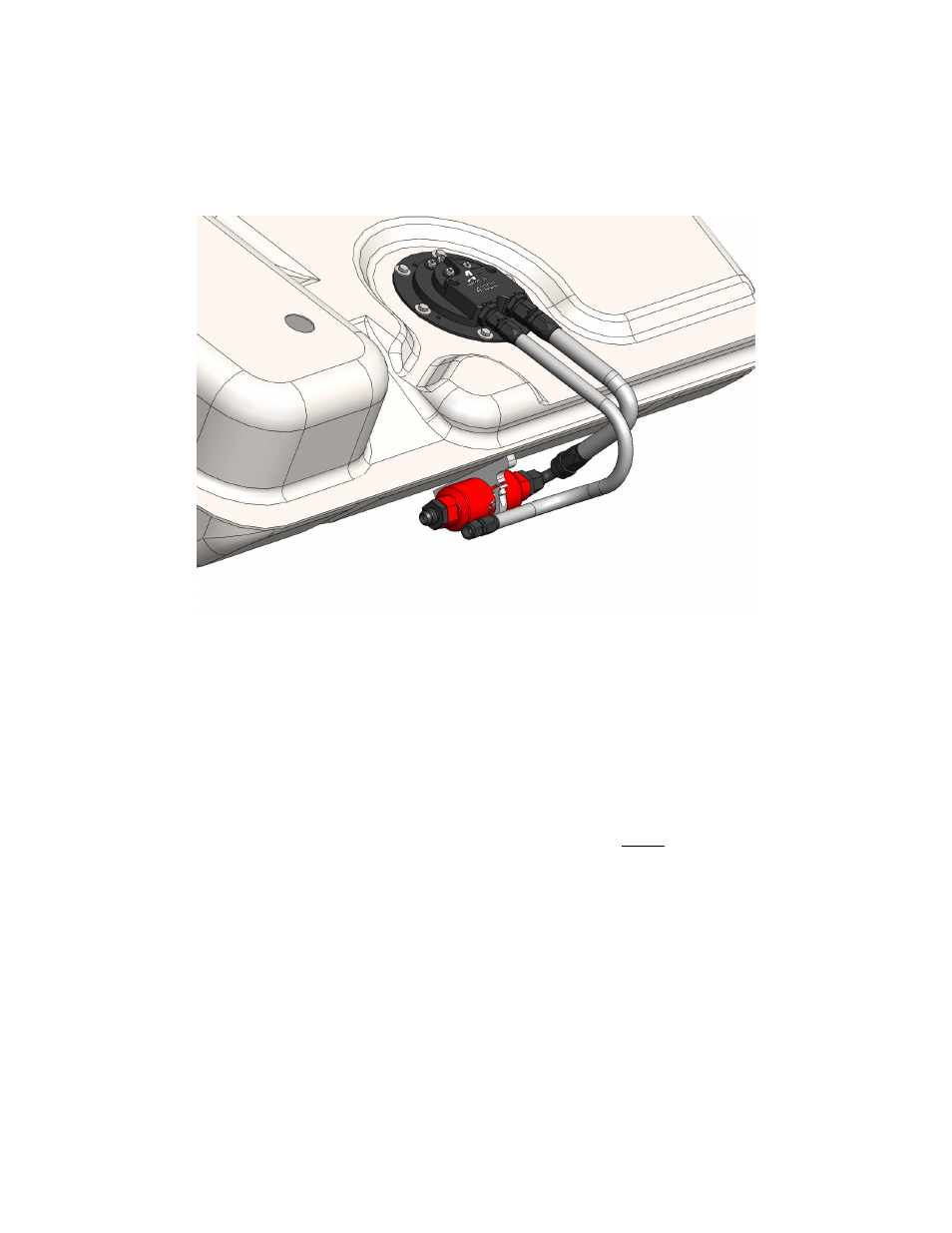
1-10. Place the fuel pump sealing gasket on top of the tank mounting ring and position the fuel pump in the tank with the
outlet/return ports facing forward (toward the front of the car). Use the supplied 6 bolts and washers to secure the
pump assembly to the tank. Place the lower tank shield onto the bottom of the new Aeromotive tank at this time.
Assemble a small section of AN-08 hose with straight hose-end on one side and 90-degree hose-end on the other.
Route from the pump outlet to the fuel filter inlet. Next, assemble a 1-2 foot section of AN-06 line with straight hose-
ends at each end. Connect one end of the AN-06 line to the return port of the pump. FIGURE 1-5
FIGURE 1-5
1-11. Before placing the fuel tank back in the car, install the small ring terminals provided onto the 10-gauge black and
red wires and connect them to the Stealth Pump (+) power and (-) ground terminals. Note: Hold the ring terminal/wire
firmly while tightening the terminal nuts and do not over tighten to avoid over- rotating the electrical bulkheads.
1-12. At this time, locate the factory fuel tank wiring harness underneath the trunk floor and, measuring 1-2 inches back
from the plug, cut the 4 wires and remove the plug. Redirect the two wires formerly connected to the OEM pump, to
the new fuel pump relay (provided). Install the small ring terminals provided on the remaining two wires and prepare
them for connection to the fuel level sending unit terminals on the Stealth Fuel Pump.
1-13. Find a suitable place to mount the provided, heavy duty fuel pump relay, it is typically mounted near the end of the
fuel tank harness, where the factory plug was removed in step 11-12 above. (Never mount the relay inside of the
fuel tank or next to fuel tank vents!). Insure the new relay and any associated parts are clear of the exhaust, any
moving suspension or drivetrain components and any possible road obstructions or debris.
1-14. Attach the OEM fuel pump wires (These typically are the red and black wires from the OEM wiring harness going to
the fuel tank) to relay terminals 85 and 86 using the supplied blue female blade connectors (See Figure 1-6 Below).
Note: Be sure to route all electrical wires clear of any moving suspension or drivetrain components, and any
exhaust components! Protect wires from abrasion and road obstructions or debris.
1-15. Find a suitable location for mounting the supplied 25-amp circuit breaker. For optimal circuit protection, the circuit
breaker needs to be mounted as close to the supply point, either the battery or alternator charging stud, as possible.
1-16. Route the supplied 10-ga red wire from the circuit breaker near the battery to the relay and terminate it with one of
the yellow, female blade connectors supplied. Connect it to terminal number 30 on the relay. At the circuit breaker
end of this wire install one of the yellow #10 ring connectors and install it one of the two studs on the circuit breaker.
Note: Be sure to route all electrical wires clear of any moving suspension or drivetrain components and any
exhaust components! Protect wires from abrasion and road obstructions or debris.