Bolt switch contact, Assembly on side of lock bolt blank, Strike plate contact, closing detector) – ABUS RS1000 Bar switching contact User Manual
Page 2: Inserting straight pin
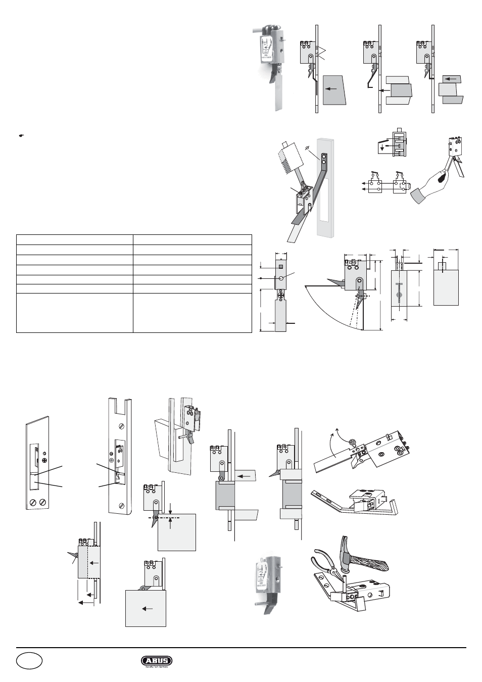
ca 4 mm
1
2
3
2 x 3,2mm
1
2
3
Bolt switch contact
(Strike plate contact, closing detector)
Assembly instructions
•
Determine fastening position for the bolt switch contact.
New feature: Possibility of assembling on side of bolt blank! (Patent!)
•
Adjust lever arm as required as shown in the examples in Figure 1, 2 or
Figure 3, or insert straight pin for assembling on side of bolt blank re-
spectively.
•
Glue drilling jig to the fastening site and drill 3.2 mm hole (2x). Figure 4.
In the case that a cable is soldered leave drilling jig for this step.
•
Depending on the application, route the connecting cable through the
cover.
•
If the version without connection cable is built, place bolt switch contact
on the angled part of the drilling jig. Figure 4. Manufacture soldered joint
in accordance with the circuit diagram. Fig. 5.
Micro switch housing is waterproof! IP 67! Connections IP 50 Seal soldered
connection if necessary or protect against moisture with a heat-shrinkable tube.
•
Remove bolt switch contact and drilling jig.
•
Create countersinking for countersunk fastening screw (M3).
•
Remove adhesive strip from drilling jig.
•
Place housing on jig (assembly aid). Figure 6
•
Put bolt switch contact in the fastening position.
•
Fasten with M3 countersunk screw provided.
NOTE! The correct screw length is calculated from the depth of the thread of the
bolt switch contact = 2 mm plus the material thickness of the strike plate!
A screw with excess length will cause a malfunction!
Technical data
VdS - Nr. G 186 105 Class C
Figure 1
Figure 2
Figure 3
NEW!
Assembly on side of lock bolt blank
Use of cover (outer doors)
Route cable through the opening in the cover before or
after soldering according to cable routing!
If there is no cover, fasten cable to housing using cable
ties.
Protection against moisture and dirt is only ensured if
the cable outlet is at the top!
Distributors
Assembly aid /
drilling jig
Switching point
10° - 15°
"Straight pin"
as additional
actuator
Bolt opening
on "striking
plate / door
frame"
Straight pin
If the initial actuation
is approximately
4 mm from the edge
of the bolt, the bolt
alignment distance
is unlimited!
Inserting straight pin
Remove fastening screw
and
remove sheet metal plate
Place bolt switch
contact on a flat
surface and insert the
drilling jig underneath
the switch actuator to
protect the surface of
the substrate!
Insert straight pin
until it is flush with the
underside of the switch
actuator.
Further example of an
application
Drilling jig
Subject to changes! Date: January 2008
Figure 4
Figure 5
Figure 6
Latch
Bolt
Control
unit
Housing, spring and lever arm
X12CrNi177 1.4310 (stainless steel)
Micro switch (changeover contact)
Gold contact 1 mA – 2 A / 30 V
Temperature range
-40 °C to +65 °C (VdS Class III)
Air humidity
Max. 95 % relative
IP rating: micro switch / connection
IP 67 / IP 50 sealed connection IP67
with cover
IP 64
Scope of delivery
(Version with LIYY 3x0,14 mm
2
connecting cable, grey Ø3,4mm
length 2m tin-coated, suitable for
LSA-Pus IDC termination technology.)
Bolt switch contact; cover; drilling; jig;
1 DIN 965 countersunk screw and A2
recessed head screw (stainless steel)
in each of the following sizes M3x5,
M3x6, M3x8, M3x10
Figure
w
ith conne
cting cable
LIYY cable
3 = white
2 = green
1 = brown
Bolt
Bolt
Bolt
Bolt
Ø 3,2mm
Screw length
= material thickness
of strike plate + 2 mm
Bolt
Bolt
Version with
connecting cable
LIYY 3x 0,14mm
2
white = 3
green = 2
brown = 1
Possible strain
relief
with cable ties
R
E
1
1
2
2
Bolt switch contacts
1
2
3
Representation in
non-actuated state
8
3
4
5
8
,7
7
,5
M3
16
3
5
7
2
3
11,5
5,5
3,3
2
8
6
18
7
Cover!
Protection against
moisture and dirt
only ensured if the cable
outlet is at the top!
90° countersinking
screw head
Ø 5,5mm
Switching
point after
approx. 8mm
Max. bolt alignment distance
in bolt opening 19 mm
RS1000
Security-Center GmbH & Co. KG www.security-center.org
GB