Functional diagram – ABUS MK4000 Door opening detector, 2m, 4-core User Manual
Page 2
UK
MK4000
Installation instructions
– Magnetic contact for gates and doors
Introduction
Top-class, heavy-duty contact for gates and doors. Extremely robust aluminium design
– highly-resistant to breakages (e.g.
when driven over by forklifts). VdS Class B certified.
Advantages of the magnetic contacts
High resistance to environmental conditions
Very large switching intervals
Extremely high resistance to wear
Simple installation
Installation
Installation is primarily made on roll-up, sliding and tilting gates and doors.
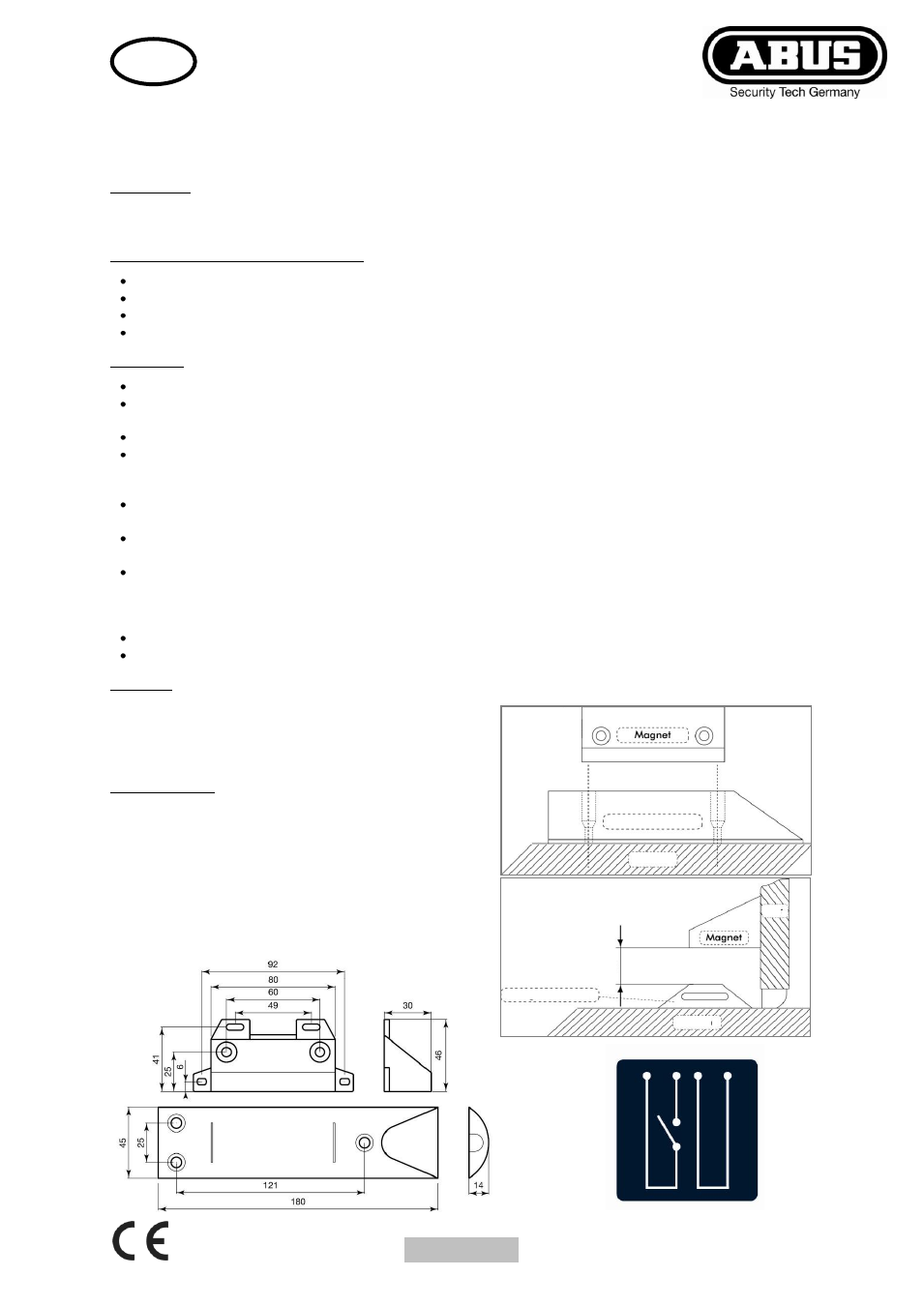
Before installation, determine the installation location so that the door contact and magnet can be fitted as shown in fig. 2.
The contact casing is fitted on the floor (a flat mounting surface is necessary).
Otherwise, only screws made of non-ferromagnetic materials may be used.
The weatherproof and mechanically stable construction of the contact casing protects the switching mechanism from
damage when driven over by vehicles with rubber tyres. To protect the product from greater loads, it must be embedded
into the ground.
The four-core cable is protected by a stainless steel protective sleeve. Two hose clips with screws and wall plugs are
included in the installation set for laying the metal sleeve properly away from the door or gate area.
When fitting the magnet casing, note the position of the two screw-holes on the contact casing, as shown in fig. 1. These
two holes determine the exact lateral position of the magnet relative to the contact.
The spacing between the contact casing and magnet casing should measure approximately 20 mm (as shown in the
diagram). If ferromagnetic materials are present in the immediate vicinity, then the switching areas must be specially
determined. The magnet should always be fitted in the middle of the non-operational area whilst adhering to VdS fitting
guidelines.
During installation, pay attention to the movement tolerance of the movable fitting surface for the magnet casing.
After installation is completed, the electrical functions on the contact must be checked (e.g. ohmmeter or circuit tester).
Warning:
The magnet loses some of its field strength if exposed to intense
heat or vibrations. This can also happen if it is placed near another
magnet
and like poles are placed together.
Technical data:
Housing material:
Aluminium
Cable:
2 m (double-insulated: 4 x 0.14 mm²)
Connections:
NC, max. contact capacity
60 V DC / 1 A / 10 W
Temperature with fixed cables:
-25 °C to +70 °C
Temperature with movable cables:
-5 °C to +50 °C
Protection class:
IP 65
Optimal spacing between sensors:
20 mm
VdS Class B:
G 191589
Functional diagram
Floor
Magnet switch
Fig. 2
Fig. 1
aproxx. 20 mm
Door
Floor
Magnet switch