Xevox duplex vds_d_uk – ABUS BW8020 Xevox Duplex VdS motion detector User Manual
Page 3
5INPLBW8020
DEUTSCH
Bedienungsanleitung XEVOX DUPLEX VdS
Plazieren des Melders
Vor der Montage des Melders sollten Sie die folgenden Punkte
berücksichtigen:
•Wählen Sie eine Stelle, von der aus die Erfassung einer Person durch
den Bewegungsmelder im Falle eines Einbruchs am besten erfolgen kann.
•Befestigen Sie den Melder in der empfohlenen Montagehöhe von 2,5m.
•Verdecken Sie nicht den Melder mit Vorhängen oder sperrigen Objekten.
•Vermeiden Sie die unmittelbare Nähe von Radiatoren, Heizungs- bzw.
Kühlrohren oder Lüftungsausgängen von Klimaanlagen.
•Plazieren Sie den Melder nicht an Stellen in Fensternähe, die
unmittelbarem Sonnenlicht oder Zug ausgesetzt sind
Installationsanweisungen
1. Öffnen Sie das Gehäuse, indem Sie den Frontdeckel entfernen. Setzen
Sie dazu einen flachen Schraubendreher im Schlitz an der Unterseite des
Melders an und hebeln Sie den Deckel vorsichtig aus der
Gehäuserückseite heraus
2. Entfernen der Leiterplatte: Lösen Sie die Befestigungsschraube auf der
Platine. Biegen Sie nun mit einem flachen Schraubendreher die
Haltenase auf der linken Seite de Gehäuses vorsichtig nach außen und
entnehmen Sie die Leiterplatte.
Anmerkung: Vermeiden Sie jegliche Berührung mit dem IR-Element.
3. Öffnen Sie die erforderlichen Montage- und Kabellöcher.
4. Führen Sie das Kabel durch die Kabeleinlässe (von der Außenseite der
Einheit) in das Gehäuse.
5. Befestigen Sie die Zugentlastung (Kabelbinder) so an der Leitung im
inneren des Gehäuses, dass der Kabel sich nicht mehr aus dem Gehäuse
heraus ziehen lässt
6. Versiegeln Sie die Öffnung der Kabeleinlässe mit Silikon zum Schutz
vor Staub und Insekten.
7. Befestigen Sie die Gehäuserückseite in einer Montagehöhe von 2m bis
3m an der Wand.
8. Verbinden Sie die Drähte mit den Anschlussklemmen (wie in Fig.1
dargestellt).
9. Setzen Sie die Leiterplatte wieder in das Gehäuse und schrauben Sie
diese an dem Bodengehäuse fest.
10. Schließen Sie das Gehäuse und vergessen Sie nicht, den Gehäuse-
deckel mit der Gehäuseschraube zu befestigen.
Betrieb und Ausrichtung
Vertikale Ausrichtung: Die Leiterplatte kann auf verschiedene vertikale
Einstellungen ausgerichtet werden (Short und Long). Dazu müssen Sie die
Platine herausnehmen und in der entsprechenden Position (Short/Long)
wieder einsetzen. Standardeinstellung ist Long.
Einstellung des Impulszählers: Der Impulszähler regelt die Anzahl von
Impulsen, die erkannt werden müssen, bevor der Melder das Alarmrelais
öffnet. Die Einstellung des Impulszählers kann über die jeweilige
Jumperstellung verändert werden. Ist der Jumper über beide PINs gesteckt
(Werkseinstellung) ist die Impulswahl 2. Wenn er nur sich nur auf einem
PIN befindet, benötigt der Melder einen Impuls bevor er auslöst.
Hinweis: Verwenden Sie für die VdS-Installation ausschließlich
Impulswahl 1.
Einstellung der LED Anzeige:
Setzen Sie die LED Brücke ein, um die LED Anzeige zu aktivieren und
entfernen Sie sie, um die Anzeige zu deaktivieren. Wenn die Brücke auf
ON steht zeigt die Farbe der LED folgende Zustände an:
- gelb:
Alarm linker Kanal
- grün:
Alarm rechter Kanal
- rot:
Alarm
Aufwärmzeit:
Nach der Versorgung mit einer Gleichspannung von 9-16V DC benötigt
der Melder eine Aufwärmzeit von ca. 3min.
Gehtest für den Melder:
Um das Linsen Abdeckmuster des Melders zu bestimmen, wird ein Gehtest
durchgeführt. Dabei laufen Sie den Erfassungsbereich des Melders
entlang. Beachten Sie hierzu das Diagramm des Erfassungsbereiches (Fig.
2). Beobachten Sie die LED um die vollständige Abdeckung
sicherzustellen. Dieser Test sollte wöchentlich durchgeführt werden.
Beschreibung der Alarmspeicherfunktion (Fig. 3)
Der Melder XEVOX DUPLEX VdS verfügt über 3 Alarm-Speicher Varianten.
Bei VdS-Installation steuert normalerweise die Alarmzentrale den Status
der LED. Um die Speicherfunktion der Anlage nutzen zu können muss der
GEH-TEST-Stecker auf OFF stehen! Die Memory-Steckbrücke ist in Abh.
von der Ansteuerung zu wählen (0V bzw. 12V).
Es stehen folgende Speichervarianten zur Verfügung:
Variante 1:
- alle Melder speichern ihre Alarmmeldungen
- nicht erkennbar welcher Melder zuerst ausgelöst hat
- Fernbedienung der GEH-TEST-Funktion durch Zentrale nicht möglich
Alle Speicher-Anschlüsse (MEM) müssen in Reihe geschaltet und mit dem
Ausgang „Speicher“ der Zentrale verbunden werden. Der GEH-TEST-
Eingang bleibt offen. Bei Scharfschaltung der Zentrale sollte am Speicher-
Ausgang ihrer Zentrale entweder +12V (HIGH) oder 0V (LOW) anliegen,
entsprechen 0V oder 12V bei Unscharfschaltung. Die LED der Melder, die
ausgelöst haben, bleiben auf AUS (Dunkelsteuerung), bis das Alarm-
system unscharf geschalten wird. Das Scharfschalten des Systems bewirkt
+12V oder 0V auf den Speichereingang des Melders und stellt diesen
zurück.
Variante 2:
- alle Melder speichern ihre Alarmmeldungen
- erkennbar welcher Melder zuerst ausgelöst hat
- Fernbedienung der GEH-TEST-Funktion durch Zentrale nicht möglich
Gehen Sie wie bei der Installation nach Variante 1 vor, mit der
Ausnahme, dass nun alle GEH-TEST-Anschlüsse der Melder miteinander
verbunden werden. Diese Anschlüsse werden jedoch nicht mit der Zentrale
verbunden. Die LED arbeitet in gleicher Weise wie in Variante 1, nur dass
beim Unscharfschalten des Systems die LED desjenigen Melders blinkt,
der zuerst eine Bewegung detektiert hat. Bei allen anderen Meldern
leuchten die LEDs stabil.
Variante 3: VdS
- alle Melder speichern ihre Alarmmeldungen
- erkennbar, welcher Melder zuerst ausgelöst hat
- Fernbedienung der GEHTEST-Funktion durch Zentrale möglich
Gehen Sie wie bei der Installation nach Variante 2 vor, mit der
Ausnahme, dass jetzt alle GEH-TEST-Anschlüsse auf einen zentralen
Ausgang, der bei Bedarf +12V oder 0V liefert, angeschlossen werden
müssen. Die LED der Melder arbeitet wie unter Variante 2. Sie können
jedoch während des Unscharfschaltens die GEH-TEST-Anschlüsse mit
+12V oder 0V versorgen (durch Tastenfeld-Befehle), so dass die Melder-
LED jedesmal EIN/AUS schalten, wenn eine Person erscheint und erfasst
wird. Die Rückstellung erfolgt wie bereits unter Variante 1 beschrieben.
Anmerkung: Bei der Durchführung eines GEH-TESTs nach Variante 3
wird der Speicher nicht gelöscht. Sobald Sie den GEH-TEST durch
Abschalten der +12V oder 0V auf den GEH-TEST-Eingang beenden,
wiederholt die LED des Melders die exakte Anzeige, die sie hatte, bevor
Sie den GEH-TEST starteten. Beachten Sie, dass nur das Wieder-Scharf-
schalten des Alarmsystems den Speicher des Melders wieder zurücksetzt.
Wenn Sie den GEH-TEST-Stecker des Melders auf ON einstellen, leuchtet
die LED des Melders jedesmal auf, wenn der Melder auslöst. Wenn Sie
den Melder nur auf diese Weise verwenden wollen, dann schließen Sie
keinesfalls den Anschluss GEH-TEST und MEM an. Lassen Sie diese
Anschlüsse einfach offen.
Technische Daten:
Betriebsspannung:
9-16V DC (nom.12VDC)
Stromaufnahme:
11mA bei 12V
Alarmkontakt:
NC, 50mA, 24VDC max.
Sabotagekontakt:
NC, 100mA, 24VDC max.
Erfassungsbereich:
15m x 15m
Installationshöhe:
2m bis 3m
Impulszähler:
1,2 (Steckbrücke)
Pyroelement:
zwei duale PIR-Elemente
Alarmdauer:
min. 2,2 Sekunde
Betriebstemperatur: -10
0
bis +55
0
C
Lagertemperatur: -20
0
C bis +60
0
C
Abmessungen (HxBxT):
107 x 60 x 48mm
Gewicht:
85g
LED Anzeige:
wählbar (Steckbrücke)
VdS-Klasse:
B
(G106507)
English
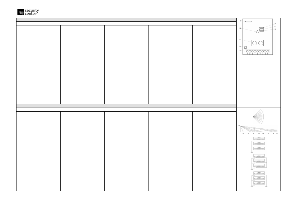
Fig. 1
A: connection Terminal/Anschlussleiste
B: tamper-Contact/Sabotage-Kontakt
C: two dual PIR-elements/zwei duale PIR-Elemente
D: LED
E: jumper memory/Steckbrücke Speicher
F: jumper pulse counter/Steckbrücke Impulszähler
G: jumper Walk-Test/Steckbrücke GEH-TEST
H: jumper LED/Steckbrücke LED
Connection Terminal/Anschlussleiste (A)
1 Memory/Speicher
2 Walk-Test/GEH-TEST
3&4 Tamper/Sabotage
5 Free/Frei
6&7 Alarm
8&9
Voltage input/Spannungseingang (GND, +12V)
Manual XEVOX DUPLEX VdS
Detector placement
Before mounting the detector, you should observe the following:
•Choose a place where it is most likely that a person will be detected by
the motion detector in the event of a burglary.
•Mount the detector at the recommended height of 2,5 meters.
•Do not conceal the detector with curtains or objects which can block
detection.
•Avoid immediate proximity to radiators, heating and refrigeration pipes,
and air conditioning ventilation outlets.
•Do not place the detector near a window where it may be exposed to
direct sunlight or draught.
Installation instructions
1. Open the housing by removing the front cover. This is done by twisting
a flat screwdriver in the slot between the cover and the base at the
bottom of the detector.
2. Remove the circuit board by loosing the PC-board holding screw.
Note: Avoid any contact with the IR component.
3. Open the required mounting and cable holes.
4. Feed the cable into the housing through the cable inlets (from the
outside of the unit).
5. Attach the strain relief with the cable inside the bottom cover. Pay
attention that the cable can not be pulled out of the cover.
6. Seal the opening of the cable inlets with silicon to protect against dust
and insects.
7. Mount the back side of the housing on the wall at a height between 2
or 3 meters.
8. Attach the wires to the connection terminal (Fig. 1).
9. Mount the circuit board and screw it tightly with the bottom cover.
10. Close the housing and don’t forget to fasten the housing cover with
the housing screws.
Operation and orientation
Vertical orientation: The circuit board can be oriented to different
vertical settings (Short, Long).Therefore you have to take out the circuit
board. Now bring the board in the desired position and attach it again
with the bottom cover. Standard setting is Long. By using Long Range
Lenses the setting is Long.
Setting the pulse counter:
The detector is supplied in the 2 pulse count mode. The adjustment of the
counter can be changed by setting the “Pulses” jumper. Is the jumper
connected with both PINs, than pulse count is 2 (normally setting). If he
is only set over one PIN, then the detector needs 1 pulse before a signal
will be sent to the alarm system.
Attention: When using the VdS installation please use only the puls
count mode 1.
Setting the LED indicator:
Removing the LED jumper disables the LED indicator. When the jumper is
ON three colours are possible for the LED:
-yellow:
left channel alarm
-Green:
right channel alarm
-red: alarm
Stabilizing the detector:
After applying 9-16Vdc, allow the detector to stabilize for circa 3 minutes
Walk testing the detector:
A walk test is performed to determine whether the detector is fully
functional. To do so, walk across the detection pattern of the detector
(refer to Fig. 2) Confirm that the LED activates and deactivates
accordingly). This test should be performed weekly.
Description of the alarm memory function (Fig. 3)
The detector XEVOX DUPLEX VdS possesses 3 alarm memory alternatives.
Normally the LED is controlled by the alarm system by using VdS
installation. To use the memory function of the system the Walk-test
connector has to be set on OFF! The setting of memory jumper depends
on the memory input (0V or rather 12V).
The following 3 memory alternatives can be chosen:
Alternative 1:
- all detectors store their alarm indications
- not identifiable, which detector was activated first
- remote control of the Walk-test through the Alarm system is not possible
All memory connections (MEM) have to be connected in series and
attached with the output “memory” of the alarm system. Leave the Walk-
test input open. If the alarm system is activated there should be installed
+12V (HIGH) or 0V (LOW) at the memory output of the system and
accordingly 0V or +12V when the system is deactivated. The LED of the
detectors, which have been activated, remains on OFF (Dark-control) until
the system will be deactivated. The activation of the system effects
+12V or 0V on the memory input of the detector and resets the memory.
Alternative 2:
- all detectors store their alarm indications
- identifiable, which detector was activated first
- remote control of the Walk-test through the Alarm system is not possible
Make the same settings as in Alternative 1, but with the exception that all
Walk-test inputs of the detectors have to be interfaced. However these
connections will not be connected with the alarm system. The LED works
like Alternative 1, with the difference that a deactivation of the system
effects a blinking on the LED, which has detected motion first. All other
LEDs lightning stable.
Alternative 3: VdS
- all detectors store their alarm indications
- identifiable, which detector was activated first
- remote control of the Walk-test through the Alarm system is possible
Make the same settings as in Alternative 2, but with the exception that all
Walk-test inputs of the detectors have to be interfaced with a central
output, which offers +12V or 0V if required. The LED of a detector works
like Alternative 2. But in this case you can feed the Walk-test-inputs with
+12V or 0V during the deactivation by using keypad orders. Thus the
detector LED can be switched ON/OFF, when a person appears and will be
detected. Make a reset as described in Alternative 1.
NOTE: If you use the Walk-test described in Alternative 3 the memory
will not be reset. As soon as the Walk-test is deactivated by switching off
+12V or 0V supply on the Walk-test input the detector LED shows
exactly the same indication like before starting the Walk-test. Pay
attention that only a newly activation of the alarm system resets the
memory of the detector. If the Walk-test connector setting is ON, the LED
of the detector lightning up each time a motion is detected. Do not
connect the inputs Walk-Test and MEM if you want to use the detector
this way. Leave this contacts open.
Technical specifications:
Input voltage:
9-16V DC (nom.12VDC)
Current consumption:
11mA at 12V
Alarm contacts:
NC, 50mA, 24VDC max.
Tamper contacts:
NC, 100mA, 24VDC max.
Coverage:
15m x 15m
Installation height:
2m to 3m
Pulse count:
selectable 1,2 (Jumper)
Pyroelement:
2 dual PIR elements
Alarm duration:
2,2 seconds minimum
Operating temperature:
-10
0
to +55
0
C (14
0
to +131
0
F)
Storage temperature:
-20
0
C to +60
0
C (-4
0
to +140
0
F)
Dimensions (HxWxD):
107 x 60 x 48mm
Weight:
85g
LED indicator:
selectable (jumper)
VdS category:
B (G106507)
Fig. 2
Alternative 1/
Variante 1:
Alternative 2/
Variante 2:
Alternative 3/
Variante 3:
Fig. 3