Rietschle thomas gmbh + co. kg page – Elmo Rietschle R-WPB User Manual
Page 5
Rietschle Thomas GmbH + Co. KG
page
5
/
23
The blower set must be stored in its original packaging in a
dry place and must be protected against dust. Compact
units in the acoustic enclosure intended for outside use can
be stored in the open air. If the blower set has been stored
for more than six months, you should (re)preserve it. For
this purpose, you can use standard preservative agents.
Storage conditions:
Temperature: -30 °C up to 40 °C
Relative humidity: up to 80%
3. I
NSTALLATION AND ASSEMBLY
Assembly in the Open Air
To install the blower set (the set including the enclosure) in
the open air, you must consider the local conditions (snow,
possibility of flooding, etc.)
Service passages and the space necessary for the set
assembly in the machine hall are shown in Appendix 3.
Acoustic enclosures designed for outside use also serve as
weather protection.
Assembly in the machine hall
The minimum dimensions of the machine hall are based on
the maximum dimensions of the compact unit (acoustic
enclosure) and the necessary 1-metre (better 1.2-metre)
operation space at the sides of the blowers (enclosures) and
between the blowers (enclosures). They are further based
on the 1.2-metre space between the wall of the discharge
section at the acoustic enclosure and the wall. The machine
hall height depends on the method chosen for handling the
machine(s).
When designing the machine hall, you must remember the
openings for the blower sets (the delivered sets are
normally assembled). The acoustic enclosure are
demountable. You should consider equipping the machine
hall with an overhead track for a crane crab or leaving
enough space for a forklift truck in order to handle those
blower sets to be maintained or repaired (necessity to
dismantle the blower and/or motor if a failure has
occurred).
The space necessary for installation of individual types of
SHARK blower sets can be derived from the dimensions
stated in the dimensional drawings.
The floor designed for installation must be flat and
dimensioned for the machine weight and anchor length.
With respect to the loading capacity, no special
requirements are stipulated for the floor design since both
the blowers and motors are dynamically balanced. The
mechanical oscillation power of the blowers and motors are
stated in Tables 3 and 4. The weight of the blower set is
distributed between its individual bases. The weight of the
delivered blower set is stated in its appropriate dimensional
drawing.
The blower set must be positioned horizontally by placing
plates under the machine bases. The permitted deviation is
1 mm for 1 metre.
WARNING
After being set in its position, the blower set must
be anchored to the floor. Otherwise, it could move
spontaneously and thus be damaged.
Working procedure for anchoring compact units and
acoustic enclosures.
1. Drill a hole and clean it;
2. Stick the anchor into the hole; and
3. Tighten the nut.
OD
L
OD1
1)
2)
3)
Compact unit –
acoustic enclosure
Anchor
OD [mm] OD1 [mm] L [mm]
WPB/WVB 120 – 430 Upat EXA M 8K
9
8
40
WPB/WVB 550 – 8300 Upat EXA 12/15
13
12
90
K 42 - K 202
Upat EXA M 8K
9
8
40
K 302 - K 802
Upat MC 12/70
13
12
65
The space and diameters of the base holes are stated in the
enclosed dimensional drawing of the compact unit. The
procedure for anchoring acoustic enclosures is the same.
You should, however, pay attention to the tightness of the
gap between the hood and the floor. After setting the hoods
in their positions, you must also level any floor unevenness
in order to prevent the sidewalls from being tight. In order
to seal the gap between the hood and the floor, you can
apply polyurethane foam, for example. The electric cable
must be laid in the floor.
If you intend to put a blower set in the hood on a half grid,
you must order a non-standard enclosure because the
bottoms of the acoustic enclosures are not soundproof.
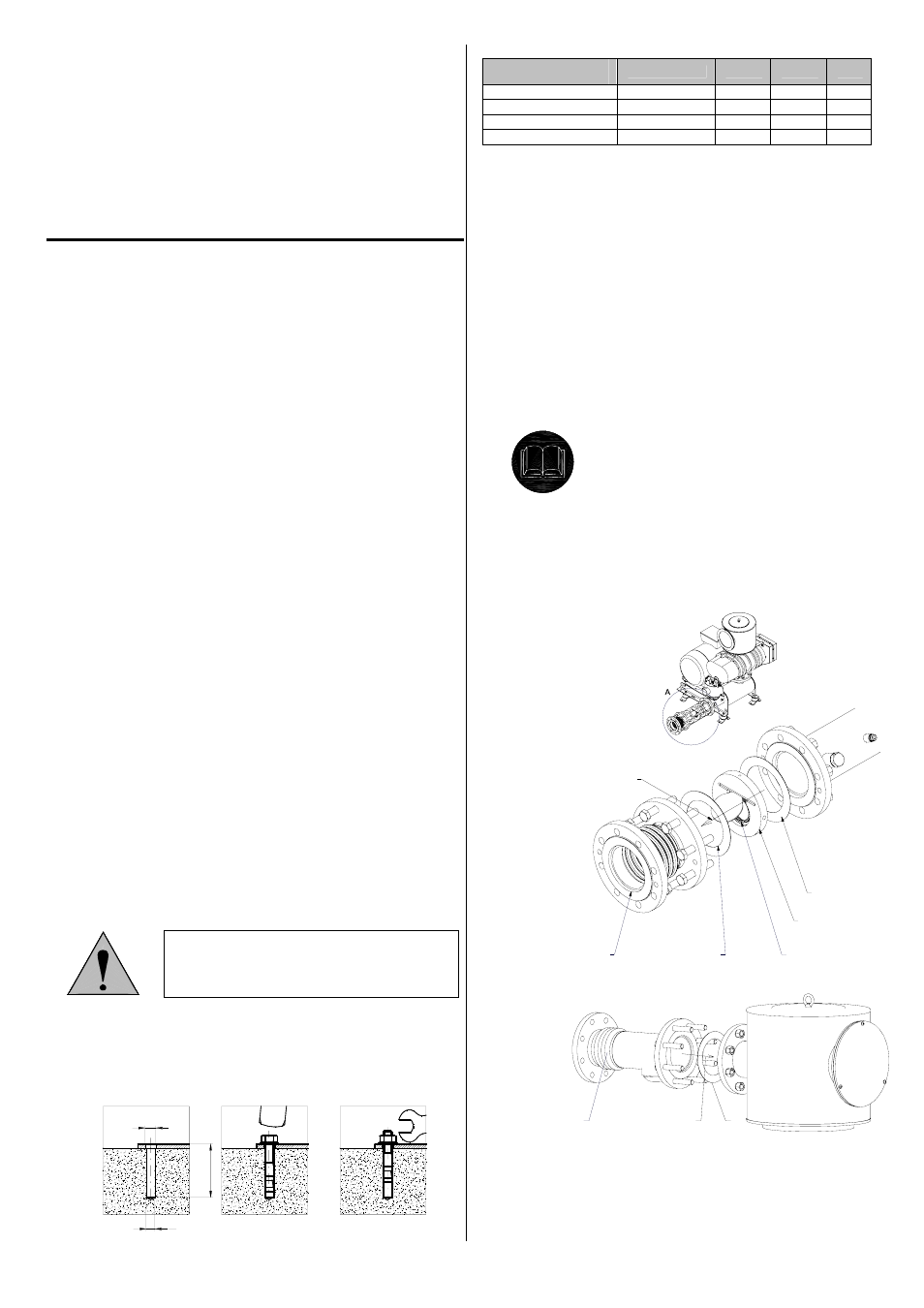
Connecting the pipeline to the SHARK compact unit
Since the entire aggregate is placed on rubber dampers, the
pipeline must be connected through flexible elements.
Otherwise, the running blower could shake the pipeline,
thus increasing the noise level. Standard compact units are
delivered with compensators for connection of the
discharge section. If a SHARK blower for vacuum is been
required or intended to be connected to the central suction,
a compensator for connection of suction is also supplied.
Delivered compensators and valves of larger blower sets
supplied with acoustic enclosures (from the K 302 type) are
not installed. These parts must be installed behind the
outlet flange of the discharge silencer or also in front of the
inlet flange of the suction silencer according to the
following pictures:
Overpressure WPB:
TOP
TOP
4
4
3
1
F
2
Overpressure WPB - central suction:
3
F
4
F Air flow
1. Non-return valve
2. O-ring
3. Compensator
4. Sealing
2.3 S
TORAGE
CONDITIONS
3.1 A
SSEMBLY
CONDITIONS
3.2 S
PACE
NECESSARY FOR
INSTALLATION
AND OPERATION
3.3 R
EQUIREMENTS
FOR ANCHORING THE
BLOWER SET OR
BLOWER
3.4
R
EQUIREMENTS
FOR CONNECTING
THE PIPELINE