Lubrication – Gorman-Rupp Pumps 810A2-4045T 1529947 and up User Manual
Page 34
80 SERIES
OM-06543
MAINTENANCE & REPAIR
PAGE E - 14
casing (1) to the base with the previously removed
hardware.
Suction Check Valve Installation
(Figure 3)
Inspect the check valve components and replace
them as required. Subassemble the check valve
weights (52 and 55) and gasket (56) using the at
taching hardware (53 and 54).
Install the check valve assembly (51), valve seat
(46), suction flange gasket (47) and suction flange
(50). Secure to the suction port with the hardware
(49).
Check the operation of the check valve to ensure
proper seating and free movement.
Final Pump Reassembly
(Figure 3)
Be sure the pump and intermediate are secure to
the engine and the base.
Install the suction and discharge lines and open all
valves. Make certain that all piping connections
are tight, properly supported and secure.
Be sure the pump and engine have been properly
lubricated, see LUBRICATION.
Before starting the pump, fill the pump casing with
clean liquid. Reinstall the fill plug and tighten. (see
OPERATION, Section C).
LUBRICATION
Seal Assembly
(Figure 3)
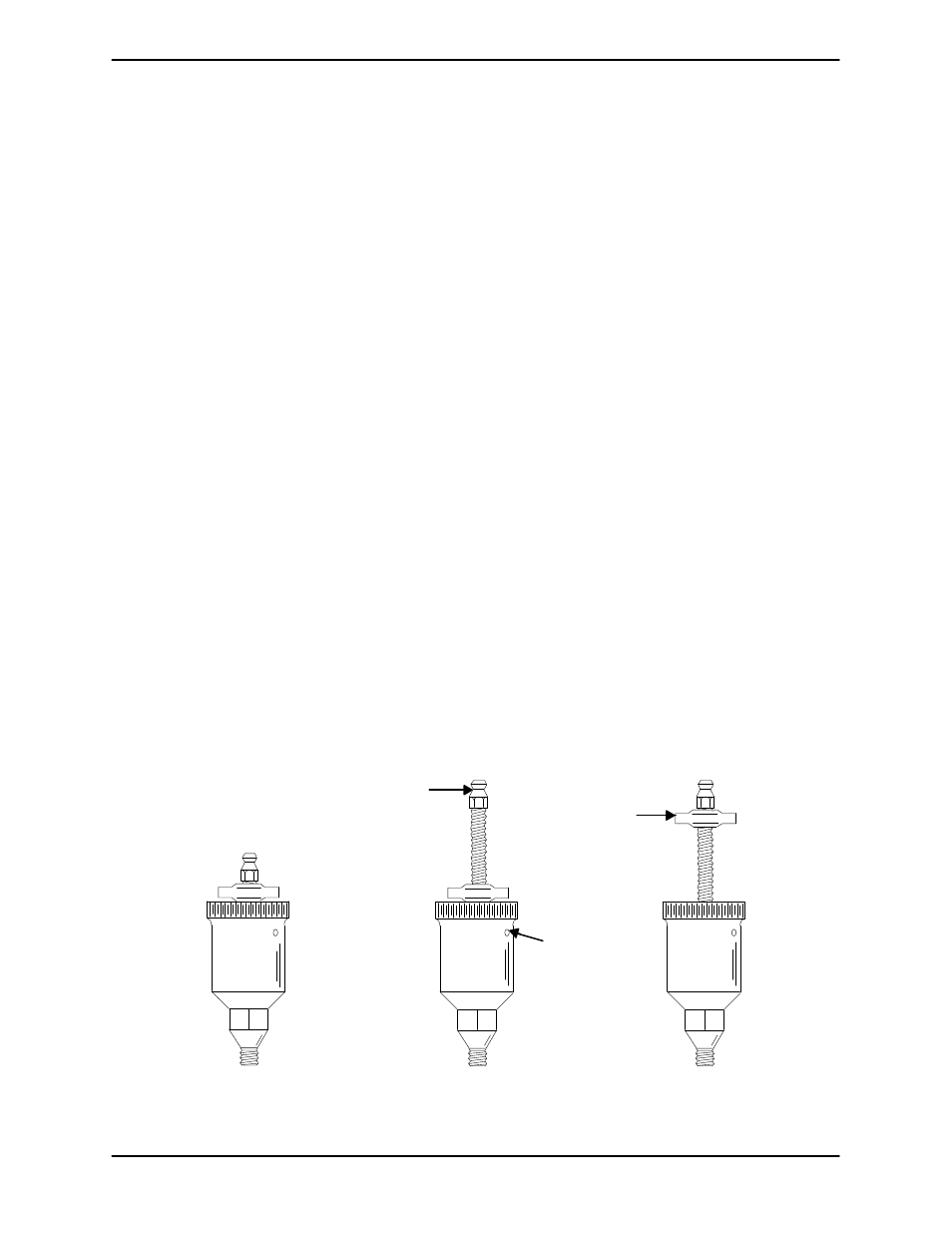
Fill the grease cup (15) through the grease fitting
with No. 2 lithium base grease until grease es
capes from the relief hole. Turn the grease cup arm
counterclockwise until it is at the top of the stem;
this will release the spring to apply grease to the
seal (see Figure 6).
GREASE
FITTING
CROSS
ARM
POSITION
WHEN
EMPTY
POSITION
FOR
FILLING
POSITION
WHEN
IN USE
RELIEF
HOLE
Figure 6. Automatic Lubricating Grease Cup