Gorman-Rupp Pumps 810A2-4045T 1529947 and up User Manual
Page 31
OM-06543
80 SERIES
MAINTENANCE & REPAIR
PAGE E - 11
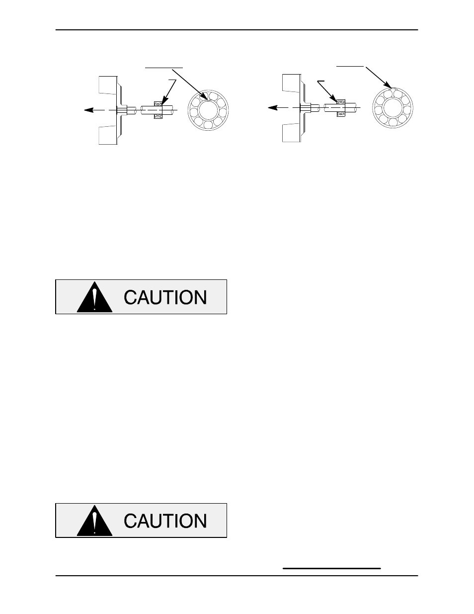
INSTALLATION OF NEW DEPARTURE OR
BCA/FEDERAL MOGAL 5300W SERIES BEARINGS
(OPEN OR ENCLOSED IMPELLERS)
INSTALLATION OF MRC/SKF 5300M OR
FAFNIR 5300W SERIES BEARINGS
(OPEN OR ENCLOSED IMPELLERS)
LOADING
DIRECTION OF
THRUST
BALL LOADING
GROOVE POSITIONED
AWAY FROM IMPELLER
GROOVE
DIRECTION OF
THRUST
LOADING
BALL LOADING
GROOVE POSITIONED
TOWARD IMPELLER
GROOVE
Figure 4. Bearing Installation
After the bearings have been installed and allowed
to cool, check to ensure that they have not moved
away from the shaft shoulders in shrinking. If
movement has occurred, use a suitable sized
sleeve and a press to reposition the bearings
against the shaft shoulders.
When installing the bearings onto the
shaft, never press or hit against the outer
race, balls, or ball cage. Press only on the
inner race.
If heating the bearings is not practical, use a suit
able sized sleeve and an arbor (or hydraulic) press
to install the bearings on the shaft until they seat
squarely against the shaft shoulders.
Press the oil seal (34) into the intermediate with the
lip positioned as shown in Figure 3.
Slide the shaft and assembled bearings into the in
termediate until the bearing is fully seated against
the bore shoulder. Be careful not to damage the oil
seal lip on the shaft threads.
When installing the shaft and bearings into
the bearing bore, push against the outer
race. Never hit the balls or ball cage.
The bearing tolerances provide a tight press fit
onto the shaft and a snug slip fit into the intermedi
ate. Replace the shaft or intermediate if the proper
bearing fit is not achieved.
Install the oil seal (30) in the bearing cap (24) with
the lip positioned as shown in Figure 3. Slide the
wavy washer (29) onto the shaft. Install the bearing
cap and gasket set (22) and secure with the hard
ware (23).
Lubricate the bearings as indicated in LUBRICA
TION at the end of this section.
Securing Intermediate And Drive Assembly To
Engine
(Figure 3)
If the drive plate assembly was removed, secure it
to the engine bellhousing with the hardware (27
and 28).
Slide the shaft splines into the drive plate. Position
the intermediate assembly with the oil hole cover at
the top and secure it to the engine bellhousing with
the hardware (20 and 21).
NOTE
Mount the intermediate guard assembly (61) on the
intermediate over the sight gauge.