Extron Electronics YCS SW2 User Guide User Manual
Page 10
YCS SW2 • Installation and Operation
Installation and Operation, cont’d
2-6
YCS SW2 • Installation and Operation
2-7
4
. Repeat
steps
2
and 3 on the other side of the YCS.
5
.
Hold the unit with the attached brackets against the
underside of the table or other furniture. On the mounting
surface, mark the location of the bracket’s screw holes.
6
.
Drill 3/32” (2 mm) diameter pilot holes, ¼” (6.3 mm) deep
in the mounting surface at the marked screw locations.
7
.
Insert #8 wood screws into the four pilot holes. Tighten
each screw into the mounting surface until slightly less
than ¼” of the screw head protrudes.
8
.
Align the mounting screws with the slots in the brackets
and place the unit against the surface, with the screws
through the bracket slots.
9
.
Slide the unit slightly forward or back, then tighten all four
screws to secure it in place.
Projector mounting
To projector-mount the YCS SW2, three optional mounting kits
are available for use with the YCS SW2.
PMK 100 Mini Projector Mount Kit
The PMK 100 is a projector mounting kit (part # 70-217-01)
designed for use with Extron 1U high, quarter-rack width
products like the VersaTools products. It allows them to be
mounted near or on a projector support.
Follow these steps to projector-mount the YCS SW2 using the
PMK 100 kit:
1
.
If rubber feet were previously attached to the bottom of the
unit, remove them.
2
.
Remove the two screws from one side of the YCS. Retain
the screws for possible later reassembly.
3
.
Attach the projector mounting bracket to the side of the
unit, using the provided machine screws.
3
1
2
OU
TP
UT
INP
UT
S
MLS
103 V
L
R
A
B
L
R
L
R
L
R
1
2
3
L
R
4
AUX
/MIX
MO
NO
AU
DIO
IN
PU
TS
PR
EA
MP
ML
C/R
S-2
32
PO
W
ER
12
V
.5A
M
AX
3
1
2
OU
TP
UT
INP
UT
S
MLS
103
V
L
R
A
B
L
R
L
R
L
R
1
2
3
L
R
4
AUX
/MIX
MO
NO
AU
DIO
IN
PU
TS
PR
EA
MP
ML
C/R
S-2
32
PO
W
ER
12V
.5
A MA
X
3
1
2
OU
TP
UT
INP
UT
S
ML
S
103 V
L
R
A
B
L
R
L
R
L
R
1
2
3
L
R
4
AUX
/MIX
MO
NO
AU
DIO
IN
PU
TS
PR
EA
MP
ML
C/R
S-2
32
PO
W
ER
12
V
.5A
M
AX
MM
X 32
V
GA
A
OU
TP
UT
1
2
1
3
OU
TP
UT
2
2
1
3
Y
C
S
S
W
2
2
1
A
U
T
O
S
W
IT
C
H
Figure 2-5 — Mounting the YCS SW2 to a back rack
support
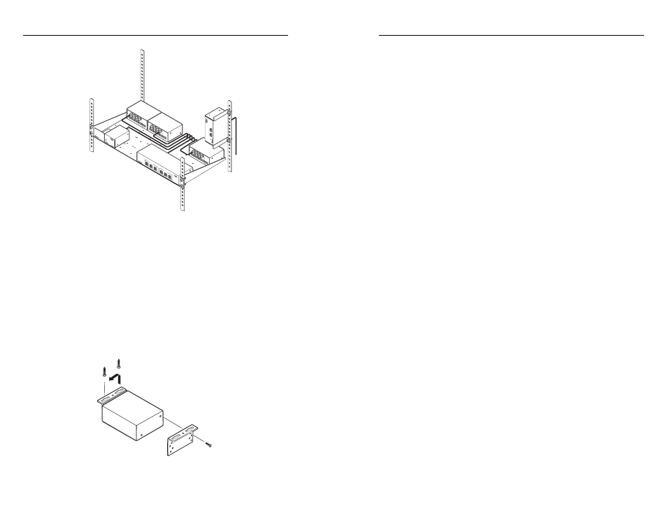
Furniture mounting
To furniture-mount the YCS SW2, use the optional VersaTools
under-desk mounting kit (part #70-212-01), as follows.
1
.
If rubber feet were previously attached to the bottom of the
unit, remove them.
2
.
Remove the two screws from one side of the YCS. Retain
the screws for possible later reassembly.
3
.
Attach one bracket to the side of the unit, using the
provided machine screws (see fi gure 2-6, below).
Figure 2-6 — Preparing the YCS SW2 for under-desk
mounting