Installation, Front panel features and cabling, Rear panel connectors and cabling – Extron Electronics WP Series Wallplates Installation User Manual
Page 2: Caution
WP SeriesWallplates • Installation
Installation
WP Series Wallplates • Installation
RCA
Audio Output
Connector
L
R
Ground (Sleeve)
Left
Right
R
L
RED
BLU
H
V
GRN
RGBHV
1
Composite video (Video) output
— A female BNC connector.
2
S-video (SVideo) output
— A 4-pin mini DIN connector for S-video
output.
Computer video output:
3
= Red,
4
= Green,
5
=
Blue,
6
= horizontal sync (H),
7
= vertical sync (V)
— Connect coaxial cables to these female BNC
connectors for the appropriate RGB signal format.
8
RCA audio output
— Unbalanced stereo
audio from the front panel RCA connectors is
output here. Wire this direct insertion captive
screw connector as shown at right.
The printing on the circuit board may
or may not match the wiring pattern.
9
Mini 3.5 computer audio output
— Unbalanced stereo audio from the
front panel mini stereo jack is output here.
Wire this connector as shown at right.
CAUTION
Connect the sleeve to ground
(Gnd). Connecting the sleeve to
a negative (-) terminal may
damage audio circuits in the
audio device, switcher, or projector.
1
3
8
8
9
5
4
7
6
2
WP 120
Rear
WP 180
Rear
Mini 3.5 mm
Audio Output
Connector
T S R
Sleeve (Ground)
Tip (Left, +)
Ring (Right, -)
R
T
S
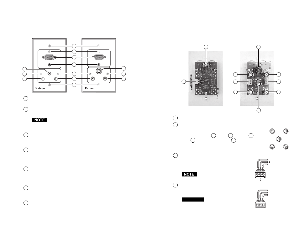
Front Panel Features and Cabling
The WP 170 and WP 180 shown below together include all the
front panel connectors that are available in the WP wallplates.
WP 170
COMPUTER
AUDIO
R
L
VIDEO
WP 180
COMPUTER
S-VIDEO
AUDIO
AUDIO
L
R
5
2
1
2
3
4
2
5
1
7
2
5
6
1
Mounting screws
— These fasten the wallplate onto the
electrical wall box, mud rings, or furniture.
2
Circuit board attachment screws
(all models) — These three
small screws fasten the circuit board to the faceplate.
Do not remove these screws while the wallplate is
attached to the wall or furniture or the circuit board may
fall into the wall or furniture.
3
Computer video input
(WP 150, WP 150 AUS, WP 170,
WP 170 AUS, WP 180) — Attach an RGB computer video source
here. Signals are routed out rear panel female BNC connectors.
4
Computer Audio input
(WP 150, WP 150 AUS, WP 170,
WP 170 AUS, WP 180) — Connect computer audio input here.
The signal is routed out the rear panel mini 3.5 mm direct
insertion captive screw connector.
5
RCA (L and R) audio input
(WP 120, WP 120 AUS, WP 130,
WP 170, WP 170 AUS, WP 180) — Connect an unbalanced stereo
audio device via these connectors. The signal is routed out the
rear panel RCA direct insertion captive screw connector.
6
Composite video (Video) input
(WP 120, WP 120 AUS, WP 170,
WP 170 AUS) — A composite video signal input here is routed
to the rear panel Video BNC connector.
7
S-video input
(WP 130, WP 180) — An S-video signal input here
is routed to the rear panel S-video connector.
3
2
Rear Panel Connectors and Cabling
The WP wallplates share a similar circuit board design: each type of
connector will be in the same place on each model, but the quantity
and selection of connectors differs from model to model. The cabling
and wiring instructions here apply to any wallplate with a particular
connector.