Extron Electronics TPS150 Setup Guide User Manual
Setup guide — tps150, Setup guide — tps150 (cont’d), Installation
This sheet provides quick start instructions for an experienced installer to
set up and operate the TPS150 switcher and transmitter system.
Installation
Step 1 — Mounting
Turn off or disconnect all equipment power
sources and mount the switcher as required.
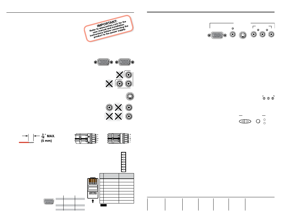
Step 2 — Transmitter inputs
Connect the applicable video and audio inputs to the TPT150 transmitter:
• RGB video inputs (inputs 1 and 2) — Connect a
high resolution video (VGA) source to this 15-pin HD
connector.
• Local monitor output (input 1 only) — Connect a high
resolution video (VGA) monitor to this 15-pin HD
connector.
N
Connect an active video input of only one format to each of
inputs 3 and 4.
• Component video input(s) (inputs 3 and 4) — Connect a
component video source to these three female BNC connectors.
• S-video input(s) (inputs 3 and 4) — Connect an S-video to this
4-pin mini DIN connector.
• Composite video input(s) (inputs 3 and 4) — Connect a composite video input
to this female BNC connector.
• Audio inputs (inputs 1 through 4) — Connect audio input
devices to the left and right RCA connectors.
Step 3 — Transmitter audio output
Connect an audio device to the transmitter’s Output Audio
connector. Wire the connector as shown below.
C
Connect the sleeves to ground (Gnd). Connecting the sleeve to a negative (-)
terminal will damage the audio output circuits.
Step 4 — Transmitter Remote Control connector
Connect a CTP150CM control panel or other contact closure device to the
Remote Control connector. For a locally constructed device, momentarily tie a
function’s pin to ground to select that function.
Step 5 — TP cable between units
Terminate a TP cable as shown at right. Use the
same standard on both ends of the cable. Connect it
between the transmitter and receiver.
Step 6 — RS-232 connectors
• Connect a PC to the TPT150 transmitter.
• Connect the
display to
the TPR150
receiver’s
RS-232 port.
Setup Guide — TPS150
Unbalanced Stereo Output
Balanced Stereo Output
L
R
Do not tin the wires!
Ring
Sleeve(s)
Tip
Tip
Ring
Sleeve(s)
Tip
Tip
NO GROUND HERE.
NO GROUND HERE.
Extron
USA - West
Headquarters
+800.633.9876
Inside USA / Canada Only
+1.714.491.1500
+1.714.491.1517 FAX
Extron
USA - East
+800.633.9876
Inside USA / Canada Only
+1.919.863.1794
+1.919.863.1797 FAX
Extron
Europe
+800.3987.6673
Inside Europe Only
+31.33.453.4040
+31.33.453.4050 FAX
Extron
Asia
+800.7339.8766
Inside Asia Only
+65.6383.4400
+65.6383.4664 FAX
Extron
Japan
+81.3.3511.7655
+81.3.3511.7656 FAX
Extron
China
+400.883.1568
Inside China Only
+86.21.3760.1568
+86.21.3760.1566 FAX
Extron
Middle East
+971.4.2991800
+971.4.2991880 FAX
Setup Guide — TPS150 (cont’d)
68-958-50
Rev. A 02 09
Step 7 — Receiver inputs
Connect applicable video devices to the TPR150 receiver:
• RGB video output — RGB/VGA
15-pin HD connector
• Component video output —
Three female BNC connectors
• S-video output — A single 4-pin
mini DIN connector
• Composite video output — A single female BNC connector
Step 8 — Power
Plug standard IEC power cords between the units’ power connectors and 100 VAC to
240 VAC, 50 or 60 Hz power sources.
Step 9 — Programming
Refer to the TPS150 User’s Manual to program the following receiver functions:
• A serial command to issue when each of the transmitter’s Input buttons is pressed
• Projector on and off commands to be issued when the receiver’s Projector Power
button is pressed
• The projector power timeout
• The projector power delays
Step 10 — Cable equalization and skew compensation
1
. Carefully use a small screwdriver to set the rear panel RGB skew controls to
minimum (fully counterclockwise).
2
. Power up the transmitter, receiver, and display.
3
. Select the highest resolution input.
4
. As needed, use the front panel low frequency control to eliminate any visible image
smear.
a
. If necessary, press and release the Cable Equalization
Select button to light the Low Frequency LED.
b
. Press the Adjust + and - button to increase and decrease
the amount of equalization applied to the output
signal’s low frequency range.
5
. As needed, use the front panel high frequency control to maximize the detail and
sharpness.
a
. If necessary, press and release the Cable Equalization Select button to light the High
Frequency LED.
b
. Press the Adjust + and - button to increase and decrease the amount of equalization
applied to the output signal’s high frequency range.
6
. If the red, green, and blue video are not properly aligned, use a small screwdriver to
gently adjust the red, green, and/or blue Skew Adjustment controls to correct for the
delay inherent in network (CAT 5/5e/6) cable.
N
The Skew Adjustment controls are sensitive. Make each adjustment carefully.
7
. Repeat steps 4 through 6 to fine tune the adjustments.
Signal
Function
Pin
1
2
3
4
5
6 - 9
—
RX
TX
—
Gnd
—
Not used
Receive
Transmit
Not used
Ground
Not used
5
1
9
6
Female
RGB / VGA
LOCAL MONITOR
OUTPUT
R-Y
B-Y
Y
VIDEO
S-VIDEO
S-VIDEO
R-Y
B-Y
Y
VIDEO
AUDIO
L
R
GND
PROJ PWR
VOL DN
VOL UP
IN4
IN3
IN2
IN1
REMOTE
CONTROL
RGB / VGA
COMPOSITE
VIDEO OUTPUT
S-VIDEO
COMPONENT
R-Y
B-Y
Y
SKEW
RED BLUE GRN
ADJ
CABLE EQUALIZATION
- ADJUST +
SELECT
LOW FREQ.
HIGH FREQ.
12345678
Insert Twisted
Pair Wires
Pins:
Pin
1
2
3
4
5
6
7
8
Wire color
White-green
Green
White-orange
Blue
White-blue
Orange
White-brown
Brown
Wire color
T568A
T568B
White-orange
Orange
White-green
Blue
White-blue
Green
White-brown
Brown
NOTE
If you are using Enhanced
Skew-Free™ A/V cable, use the
TIA/EIA T568A standard only.