Extron Electronics SC 210 User Guide User Manual
Page 2
Turning a DIP switch ON will override Automatic Sync Detection.
Video
Gain ................................................ Unity
Bandwidth ..................................... 250 MHz (-3dB)
Video input
Number/signal type ................... 1 analog RGBHV, RGBS, RGsB, RsGsBs
Connectors ................................... 5 BNC female
Minimum/maximum levels ....... Analog ....... 0.3V to 1.5V p-p with no offset at
unity gain
Impedance .................................... 75 ohms
Horizontal frequency .................. 15 kHz to 150 kHz
Vertical frequency ....................... 40 Hz to 140 Hz
Return loss .................................... -37dB @ 5 MHz
Maximum DC offset .................... 2V
Video output
Number/signal type ................... 1 analog RGBHV, RGBS, RGsB
Connectors ................................... 5 BNC female
Minimum/maximum levels ....... Analog ....... 0.3V to 1.5V p-p
Impedance .................................... 75 ohms
Return loss .................................... -20dB @ 5 MHz
DC offset ....................................... ±10mV maximum with input at 0 offset
Sync
Input type ..................................... RGBHV, RGBS, RGsB, RsGsBs
Output type .................................. RGBHV, RGBS, RGsB
Input level ..................................... RGBHV, RGBS .......... TTL/analog .. 5V p-p
RGsB, RsGsBs ........... analog ............ 0.3V
Output level .................................. TTL ............. 4V to 5V p-p
Input impedance .......................... 510 ohms
Output impedance ....................... 75 ohms
Max input voltage ........................ 5V p-p
Input sensitivity ........................... 0.6V to 5V p-p
Max. propagation delay .............. 130 nS
Max. rise/fall time ....................... 4 nS
Polarity .......................................... RGBHV, RGBS .......... positive or negative
(follows input)
RGsB, RsGsBs ........... negative
General
Power ............................................ 100VAC to 240VAC, 50/60 Hz, 10 watts, internal,
auto-switchable
Temperature/humidity .............. Storage -40° to +158°F (-40° to +70°C) / 10% to
90%, non-condensing
Operating +32° to +122°F (0° to +50°C) / 10% to
90%, non-condensing
Rack mount .................................. Yes, with optional shelf, #60-190-01
Enclosure type .............................. Metal
Enclosure dimensions ................. 1.75" H x 8.75" W x 9.4" D (1U high, half rack
width)
4.4 cm H x 22.2 cm W x 23.9 cm D
Product weight ............................. 3.0 lbs (1.4 kg)
Features
The SC 210 is a 250 MHz sync processing device. Any type of
RGB signal can be converted to any other type. This is determined
by cable connections and DIP switch settings. For example:
Input
Output
RGsB
RGBS, RGsB, or RGBHV
RGBS
RGsB, RGBS, or RGBHV
RGBHV
RGsB, RGBHV, or RGBS
RsGsBs
RGsB, RGBS or RGBHV
The SC 210 can also be used as a sync stabilizer to eliminate jitter.
The SC 210 automatically strips incoming sync from the red, green
& blue video channels.
Operation
Power LED: Indicates if the SC 210 is receiving power.
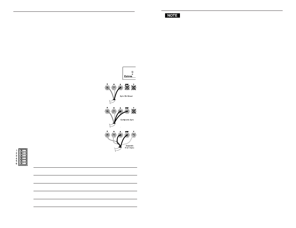
Automatic Sync Output Detection
Sync can be output in three ways, depending
on the impedance detected through the
output cables:
Impedance = 75 ohms on R, G, and B,
or up to 1 kohms on Sync lines.
• Impedance on only R, G & B channels,
output = Sync On Green.
• Impedance on only R, G, B, & H/HV channels,
output = Composite Sync.
• Impedance on R, G, B, H/HV & V channels
output = Separate H & V Sync.
DIP Switch Settings
As stated above, the SC 210 outputs sync
according to the impedance detected on the
output cables. However, the DIP switch
settings take priority. If a switch is set, it forces
a condition, regardless of what is detected.
The DIP switch settings are shown below. In
the default positions (all switches OFF), sync output is determined
by the impedance detected through the output cables.
Sw#
PositionFunction
1
ON
Does not allow Sync on Green
OFF-normal Automatic Sync Output Detection
2
ON
Always Separate H and V Sync
OFF-normal Automatic Sync output Detection
3
ON
Always Negative Sync
OFF-normal Sync output polarity follows input polarity
4
ON
Remove serration pulses (if Sw 6 = Off)
OFF-normal Serration pulses pass through
5
ON
Vertical Sync Width = 500 µs (if Sw 6 = Off)
OFF-normal Vertical Sync Width = 150 µs
6
ON
LCD Sync Processing (disables Sw 4 & 5)
OFF-normal Sync Processing
Features and Operation
1
Extron • SC 210 • User’s Guide
Operation and Specifications
Extron • SC 210 • User’s Guide
2