Extron Electronics SGS 408 DVI User Guide User Manual
Page 2
SGS 408 DVI Connector • Installation
SGS 408 DVI Connector • Installation
Installation
3
2
Installing the DVI Connector
The DVI connector card may be installed in the SGS 408 by
following the instructions and illustrations shown below. Before
the DVI connector card can be installed, the internal components
of the SGS 408 must first be accessed.
Internal access
To gain access to the internal components, do the following:
1.
Remove the power cable from the SGS 408 and from the
power source.
Do not open the cover of the switcher without unplugging
the power cord.
2.
If the SGS 408 switcher is rack mounted, remove the input
and output cables from it and remove the unit from the
rack. If the switcher is not rack mounted, you do not need
to remove the input and output cables.
3.
Remove 16 screws from the sides and top of the cover and
two #10 screws from the upper half of the front panel
(figure 1).
Figure 1 — Removing the cover
4.
Remove the cover by slightly lifting each side alternately
until the cover is free.
Reverse this procedure to reinstall the cover.
Installing the DVI connector card
After following the instructions in “Internal access” to remove
the cover, do the following:
1.
Remove and retain the two screws that hold the DVI
connector cover in place (figure 2), and set the cover aside.
You will not need it.
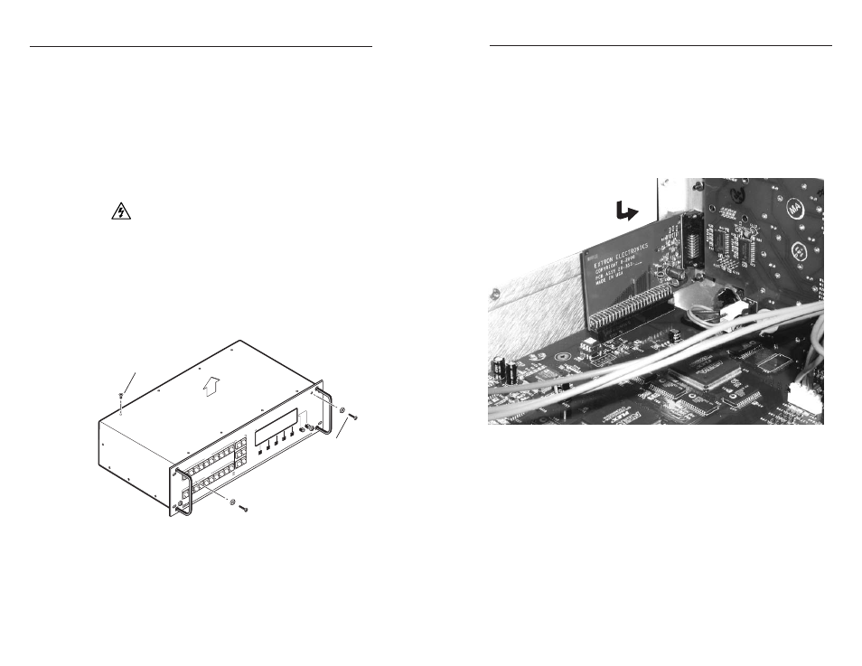
Figure 2 — Installing the DVI connector card
2.
Insert the DVI connector through the hole that was created
in the rear panel in step 1.
3.
Carefully align the DVI circuit card 50-pin connector with
socket J3 on the SGS 408 circuit board. With the pins
aligned, press down gently on the DVI circuit card. Check
the alignment of the DVI circuit card and socket J3.
Use the two previously removed DVI connector cover
screws to fasten the DVI connector in place.
4.
Reinstall the cover of the SGS 408.
After removing the DVI connector cover,
insert the DVI connector through the
opening in the chassis and press
the circuit card evenly into the socket.
PR
OG
RA
M
FR
EE
ZE
BL
AC
K
1
2
3
4
5
6
7
8
CU
T
TA
KE
PR
OG
RA
M
PR
EV
IEW
OU
TP
UT
RA
TE
EF
FE
CT
TR
AN
SIT
IO
N
SGS
408
SE
AM
LE
SS
G
RA
PH
IC
SW
ITC
HE
R
INP
UT
1
2
3
4
TR
AN
SIT
IO
NS
EF
FE
CT
S
RC
P C
OM
MU
NIC
AT
IO
N
PR
EV
IEW
FR
EE
ZE
BL
AC
K
1
2
3
4
5
6
7
8
Tx
Rx
Remove #10 screw
(two plcs) each side
of front plate.
Lift cover
straight up
Remove (16)
screws from
top and sides.