Extron Electronics PowerCage FOX 4G Tx_Rx DVI and VGA Setup Guide User Manual
Powercage fox 4g tx/rx dvi and vga setup guide, Installation, Step 1 — mounting
This guide provides instructions for an experienced installer to set up and operate the Extron
®
PowerCage
FOX 4G Tx/Rx DVI and PowerCage FOX 4G Tx/Rx VGA fiber optic video and audio extenders.
NOTES: PowerCage transmitters (Txs) can output signals to any PowerCage Fox 4G,
FOXBOX 4G, or FOX 500 VGA or DVI device.
PowerCage receivers (Rxs) can accept signals from any PowerCage 4G,
FOXBOX 4G, or FOX 500 VGA or DVI device.
Installation
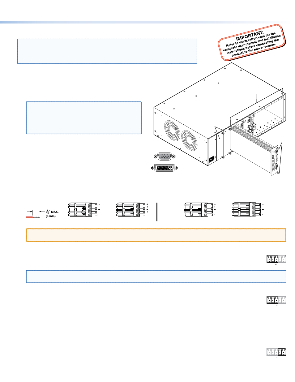
Step 1 — Mounting
Install the Tx, Rx, or both in PowerCage enclosures as required.
NOTES: • PowerCage boards are hot-swappable.
•
Ensure the boards are flush with the
rear of the enclosure and the screws
tightened securely before applying
power.
Step 2 — Input and Output Connections
a.
Connect an RGB or DVI video source to the Input connector
on the transmitter.
b.
Connect an RGB or DVI display to the Output connector on
the receiver.
c.
Connect a balanced or unbalanced, stereo or mono audio
input to the transmitter via the Audio Input captive screw connector and
a balanced or unbalanced stereo or mono audio device to the receiver via the Audio Output captive screw connector. See the
drawing below.
Unbalanced Stereo Output
Balanced Stereo Output
L
R
Ring
Sleeve(s)
Tip
Tip
Ring
L
R
Sleeve(s)
L
R
L
R
Tip
Tip
NO GROUND HERE.
NO GROUND HERE.
Unbalanced Stereo Input
Balanced Stereo Input
Ring
Sleeve (s)
Tip
Sleeve
Tip
Sleeve
Tip
Tip
Ring
Do not tin the wires!
CAUTION: For unbalanced audio, connect the sleeves to the ground contact. DO NOT connect the sleeves to the negative (-)
contacts).
d.
If you want the PowerCage FOX 4G units to pass serial data or control signals, such as for serial control of a
RS-232
OVER FIBER
Tx Rx
projector, connect the master device to the transmitter and the slave device to the receiver via the first three poles
of the RS-232 Over Fiber captive screw connectors on both units.
NOTE: For RS-232 responses (from the receiver to the transmitter), you must install the cable in step 2d and leave the
receiver in normal configuration.
e.
For serial control of the transmitter and receiver, connect a host device, such as a computer, to the Remote RS-232
1 2
REMOTE
RS-232
Tx Rx
ALARM
port on either unit via three poles (Tx, Rx, and
_
) of the Remote RS-232/Alarm 5-pole captive screw connector on
either unit. The protocol for these ports is as follows:
•
9600 baud
•
no parity
•
8 data bits
•
1 stop bit
•
no flow control
Refer to the PowerCage FOX 4G Tx/Rx User Guide for detailed information about using the Simple Instruction Set (SIS™)
commands and the Windows
®
-based FOX Extender program to set up and operate the transmitter and receiver and to take
advantage of the various adjustments and test patterns available on the PowerCage FOX 4G units.
f.
For remote monitoring of the status of the Rx optical link on either the transmitter or receiver, connect a locally
1 2
REMOTE
RS-232
Tx Rx
ALARM
constructed or obtained device to the two Alarm poles of the Remote RS-232/Alarm 5-pole captive screw connector
on that unit. The two poles are shorted together when no light is detected.
M
O
N
O
A
U
DIO OUTPU
T
1
2
S
H
A
R
P
GAIN
Y/VI
D
C
INPU
T
Po
we
rCa
ge
MT
P R
AV
Tx
R
x
HD/SDI INPU
T
H
D/SDI OUTPUTS
MODE
Po
we
rCa
ge
FO
X 3G
HD-SD
I
1
2
R
E
M
O
TE
RS-232
RS-232
O
VER FIBE
R
T
x
R
x
Tx
ALARM
Rx
V
ID
E
O
1
2
3
4
Po
we
rCa
ge
FO
X 2G
Rx
AV
T
x
R
x
L
R
A
U
D
IO
5A MAX.
100-240V
50/60H
z
1
2
REM
O
T
E
RS-232
RS-232
O
VER FIBE
R
Tx Rx
Tx
ALAR
M
Rx
OUTPUT
RG
B
Po
we
rCa
ge
FO
X 4G RX
RG
B
Tx Rx
L
R
A
UDI
O
16 available single board slots or
8 double board slots
Power
Supply
Screws
RGB
DVI
1
PowerCage FOX 4G Tx/Rx DVI and VGA Setup Guide