Wpb 109 wallplate • installation guide (continued), Direct insertion captive screw, Caution – Extron Electronics WPB 109 Wallplate User Manual
Page 2: Cable preparation for audio connections, Do not tin the wires, Unbalanced input, Unbalanced output
WPB 109 Wallplate • Installation Guide (Continued)
Extron Headquarters
+1.800.633.9876 (Inside USA/Canada Only)
Extron Asia
+65.6383.4400
Extron China
+86.21.3760.1568)
Extron Korea
+82.2.3444.1571
Extron Europe
+31.33.453.4040
Extron Japan
+81.3.3511.7655
Extron Middle East
+971.4.299.1800
Extron India
+91.80.3055.3777
© 2013 Extron Electronics — All rights reserved. All trademarks mentioned are the property of their respective owners.
www.extron.com
68-1162-50
Rev. A 01 13
Tip
Sleeve(s)
Ring
Ring
Tip
Tip
Sleeve
Sleeve
Tip
Unbalanced Input
TRS Connector
RCA Connector
Left
Right
Left
Right
Balanced Input or Output
Balanced Mono Audio
Unbalanced Stereo Audio
Balanced Audio
Wiring
Unbalanced Audio
Wiring
Source
Reference
Tip
Sleeve
Ring
Tip
Sleeve
Direct Insertion
Captive Screw
Unbalanced Output
Left
Tip
Sleeve(s)
NO Ground Here
NO Ground Here
Tip
Right
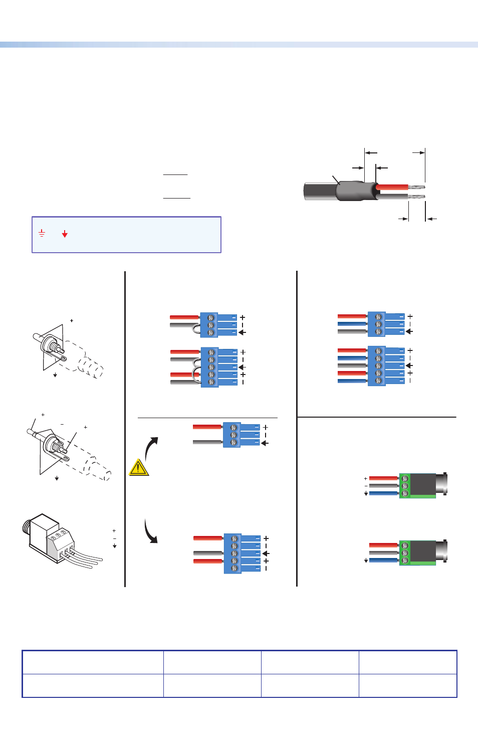
CAUTION
For unbalanced audio, connect the
sleeve(s) to the ground contact.
DO NOT
connect the sleeve(s) to the
negative (-) contacts.
Tip
Sleeve
NO Ground Here
Ring (R)
Ring
Tip (T)
Tip
Tip
Tip
Sleeve (S)
Ring (R) = Right Channel
Tip (T) = Left Channel
Sleeve (S)
(input or output)
(input or output)
Sleeve
Sleeve
Sleeve (S)
Ring (R)
Tip (T)
3.5 mm Audio Jack
T R
S
Heat
Shrink
1/8"
(3 mm)
7/8"
(22 mm)
3/16" (5 mm) Max.
Cable Preparation For Audio Connections
The length of the exposed wires in the stripping process is critical.
The ideal length is
3/16" (5 mm).
• If the stripped section of wire is longer than
3/16", the exposed
wires may touch, causing a short circuit between them.
• If the stripped section of wire is shorter than
3/16", the wires can
be easily pulled out even if tightly fastened by the captive screws.
Do not tin the wires!
Tinned wire does not hold its shape and can become
loose over time.
NOTE: Audio ground pins may be labeled as
or . The wiring and function are the same,
whichever way your product is labeled.
7.
Connect the appropriate input or output devices to the front panel connectors.
8.
Test the system and resolve any cabling or signal issues.
2