Extron Electronics Systimax Connector Wiring Guide User Manual
Systimax connector wiring guide, Systimax connector wiring guide, cont’d
68-1565-01
Rev. A
05 08
Extron Electronics, USA
1230 South Lewis Street
Anaheim, CA 92805
800.633.9876 714.491.1500
FAX 714.491.1517
Extron Electronics, Europe
Beeldschermweg 6C
3821 AH Amersfoort, The Netherlands
+800.3987.6673 +31.33.453.4040
FAX +31.33.453.4050
Extron Electronics, Asia
135 Joo Seng Rd. #04-01
PM Industrial Bldg., Singapore 368363
+800.7339.8766 +65.6383.4400
FAX +65.6383.4664
Extron Electronics, Japan
Kyodo Building, 16 Ichibancho
Chiyoda-ku, Tokyo 102-0082
Japan
+81.3.3511.7655 FAX +81.3.3511.7656
www.extron.com
Systimax Connector Wiring Guide
Systimax Connector Wiring Guide, cont’d
Installation
1. Determine which wiring scheme (T568A
or T568B) to use. Note the associated
color codes on the two labels located on
the sides of the connector. The labels
also include the connector pin numbers.
2. Remove about 1" (25 mm) of the cable
jacket. If the cable includes a center
spline (stiff wire separator inside the
cable), remove it also.
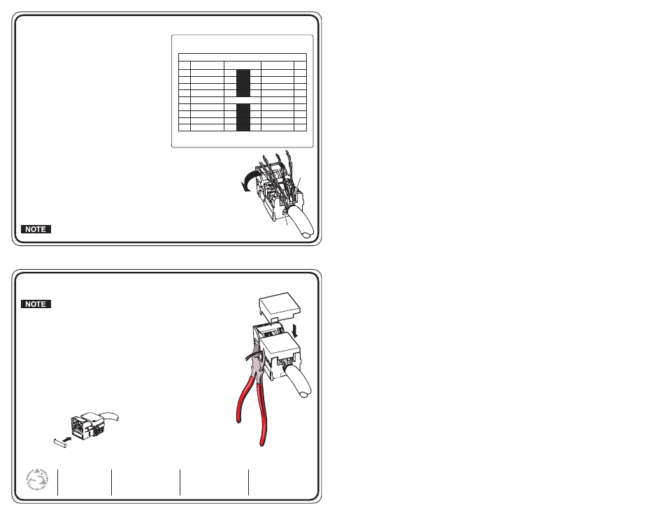
3. Route the wires for termination using
the color code in the table at right. See
the table for hole (h) and slot (s) wire
routing designations.
4. Insert the wire pairs into the connector
body with the brown and blue wires
inserted into the right side slot (s) and hole (h), respectively.
The orange and green wires are inserted into the left side
hole (h) and slot (s). Refer to the above table.
5. Pull the wires tight so that the cable jacket ends at the connector
body. Avoid twisting the wires. Carefully seat the wires into the wire
terminals without any crossover or rearrangement.
Be sure that there is enough slack in the twisted pairs, and do not
place the cable jacket into the termination field.
For some cables, wires for pin numbers 2, 4, 6, and 8
may have a white stripe. This is equivalent to cables with
solid wires for the same pin numbers.
6. If you are using an impact tool with the M110 blade, set the tool
to HI impact, and position it perpendicular to the connector.
Otherwise, align the insertion cap prongs with the grooves of
the connector body and firmly press the insertion cap into the
connector body until the cap snaps into place.
7. Using wire cutters, trim any excess protruding wires flush with
the connector body. See diagram at right.
8. An icon insert (included) can be inserted in the front face of
the connector if desired, as shown below.
Hole
(left)
Slot
(right)
T568A
Green 2
7 White/Brown
White/Green
1
8
Brown
White/Orange
3
5
White/Blue
Orange
6
4
Blue
T568B
Orange 2
7
White/Brown
1
8
Brown
White/Green
3
5
White/Blue
Green
6
4
Blue
Pin Number
Wire Color
Wire Color
Left
side*
Right
side*
* The wires enter the connector through the end hole (h) or the top slot (s) on
the left and right sides of the connector as seen from the cable end. See the
diagram below.
T568A & T568B
Pin Wiring Assignments
White/Orange
s
s
h
h
h
h
s
s
h
h
s
s
s
s
h
h