Feed wires into guide, Insert wires into rj-45 connector, Crimp wires – Extron Electronics Extron Shielded DTP RJ-45 Plug for DTP26 Cable User Manual
Page 2: Test cable, Extron contact information, Extron
Extron
®
Shielded DTP RJ-45 Plug for DTP26 Cable Termination Kit (continued)
68-1813-01
Rev.
C
11 10
Extron USA - West
Headquarters
+800.633.9876
Inside USA and
Canada Only
+1.714.491.1500
+1.714.491.1517 FA
X
Extron USA - East
+800.633.9876
Inside USA and
Canada Only
+1.919.863.1794
+1.919.863.1797
FAX
Extron Europe
+800.3987.6673
Inside Europe Only
+31.33.453.4040
+31.33.453.4050 FAX
Extron Asia
+800.7339.8766
Inside Asia Only
+65.6383.4400
+65.6383.4664 FAX
Extron Japan
+81.3.3511.7655
+81.3.3511.7656
FAX
Extron China
+400.883.1568
Inside China Only
+86.21.3760.1568
+86.21.3760.1566
FAX
Extron Middle East
+971.4.2991800
+971.4.2991880
FAX
© 2010 Extron Electronics All rights reserved.
www.extron.com
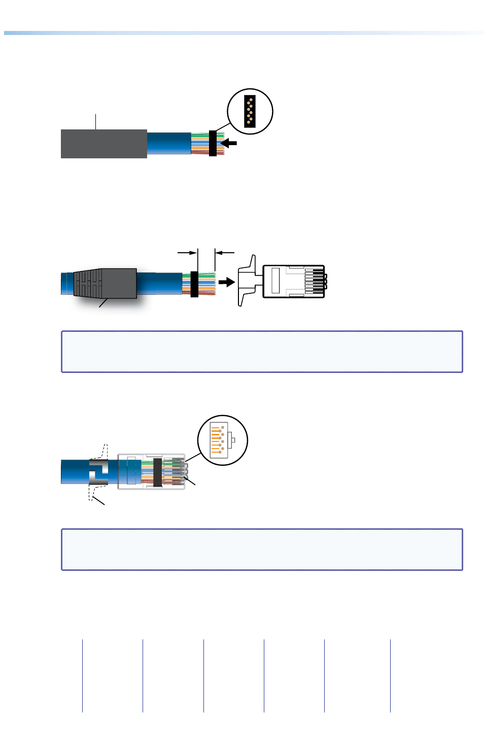
7.
Feed the individual wires, in the correct order, through the open front face of the
plastic guide and out through the individual holes at the rear. The rear of the guide
should be seated against the end of the foil shield with CAT 7 or DTP26 cables and
against the braid for all other types of twisted pair cables.
Insert wires through the open front face and out
through the holes in the rear face of the guide.
Guide
(rear face
shown)
Heat Shrink Tubing
or Strain Relief (Optional)
8.
Cut the wires to 0.3 inches (7.6 mm), as shown in the figure below. The total length of
exposed wire should not exceed 0.6 inches (15.2 mm).
9.
Insert the guide and wires into the RJ-45 connector, making sure the wires pass the
crimping teeth of the connector.
Insert into RJ-45
Connector
0.3"
Strain Relief
Strain Relief
NOTE: Ensure the wires are in the correct order (see chart on previous page) and
the bottom of the connector is next to the braid shield that was folded under the
cable in step 6.
10.
Insert the connector into the termination tool and crimp it to secure the connector to
the cable. Use pliers to secure the connector tabs around the cable and the ground.
Crimp connector.
NOTE:
Ensure conductors are
seated properly under
contacts.
Connector Tab
NOTE: To ensure correct grounding throughout the cable, the braid shield, folded
back in step 6, must make contact with the shielded RJ-45 connector on both
ends of the cable.
11.
If a strain relief is present, slide it forward to cover the cable and the first 0.4 inches
(10.2 mm) of the RJ-45 connector.
12.
Test both ends of the cable for conductivity.