Smb 1 • installation guide (continued), Cabling, Install the touchpanel – Extron Electronics SMB 1 Installation User Manual
Page 2
SMB 1 • Installation Guide (Continued)
68-2298-01 Rev. A
02 14
Extron Headquarters
+1.800.633.9876 (Inside USA/Canada Only)
Extron USA - West
Extron USA - East
+1.714.491.1500 +1.919.850.1000
+1.714.491.1517 FAX
+1.919.850.1001 FAX
Extron Europe
+800.3987.6673
(Inside Europe Only)
+31.33.453.4040
+31.33.453.4050 FAX
Extron Asia
+65.6383.4400
+65.6383.4664 FAX
Extron Japan
+81.3.3511.7655
+81.3.3511.7656 FAX
Extron China
+86.21.3760.1568
+86.21.3760.1566 FAX
Extron Middle East
+971.4.299.1800
+971.4.299.1880 FAX
Extron Korea
+82.2.3444.1571
+82.2.3444.1575 FAX
Extron India
1800.3070.3777
Inside India Only
+91.80.3055.3777
+91.80.3055.3737 FAX
© 2014 Extron Electronics All rights r
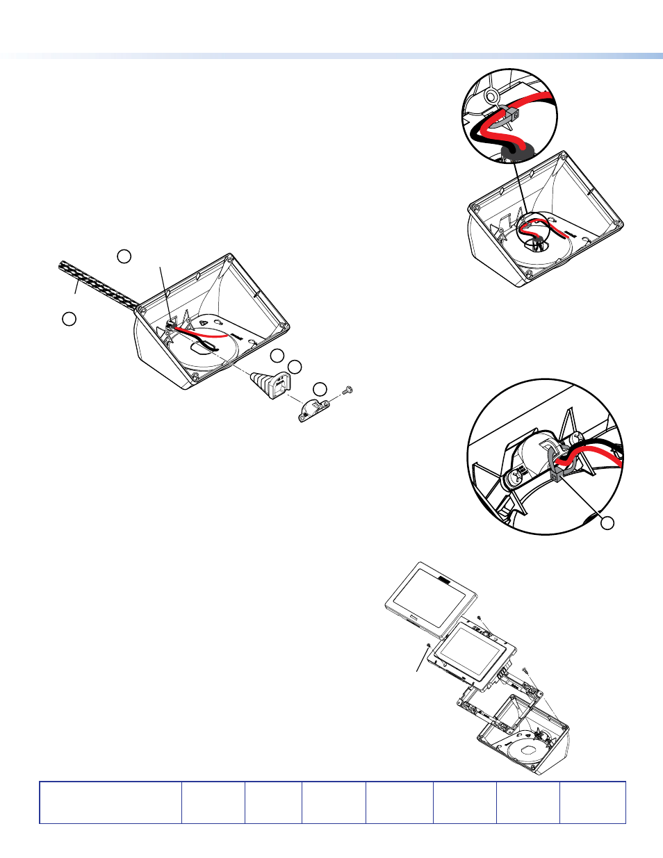
Cabling
Run cable to the SMB 1 before installing the touchpanels. Leave some slack in the wiring
during installation.
From Underneath
1.
Bundle the wiring using the provided cable wrap.
2.
Feed it from under the furniture through the hole drilled in the table in step 3 of the
previous section.
3.
Secure the cable with one or more zip ties as shown in the inset of the figure to the
right.
From the Rear
Cover cables
with Cable Wrap
Rear Cable
Access Opening
Strain Relief Boot
Strain Relief Clamp
1
2
3
4
5
#4 screws (2)
1.
Remove the rear cable access pop-out (
a
in figure above).
2.
Bundle the wiring using the provided cable wrap and feed it through the rear cable
access opening (
b
).
3.
Trim the strain relief boot to fit the wiring and cable wrap (
c
).
4.
Slide the boot over the wiring and cable wrap and into the rear cable access opening (
d
).
5.
Place the strain relief clamp into the boot and fasten it with the provided
#4 sheet metal screws (
e
).
6.
Secure the wires and cable wrap with a zip tie (
f
in the figure to the right).
Install the TouchPanel
1.
Secure the wall plate adapter to the SMB 1, using the four provided
#6 sheet metal screws.
2.
Run cables through the rear cable pop-out or the hole in the base
and connect them to the back panel of the touchpanel (see the
TLP PRO 320M User Guide or the TLP PRO 520M User Guide at
).
3.
Press the touchpanel onto the wall plate adapter. Four catches hold
the touchpanel in place.
4.
Remove the bezel and attach the touchpanel to the wall plate
adapter with the two Phillips head screws (#4-40 x ¼") that are
provided with the touchpanel. For extra security, these screws can be
replaced with two security screws of the same size (not provided).
5.
Replace the bezel.
6
Wall Plate Adapter
TLP Pro
SMB 1
#6 Sheet Metal
Screws (4)
Bezel snaps to unit
(2 places on top and 2
places on the bottom)
#4-40 x ¼"
Screws (2)