Configuration, Sync impedance dip switches, Mute control – Extron Electronics P-2 DA12 Series Setup Guide User Manual
Page 2: Caution, Switch function sync impedance (ohms) on off
Setup Guide — P/2 DA8 and P/2 DA12 Series (cont’d)
68-1475-50
Rev. A
01 10
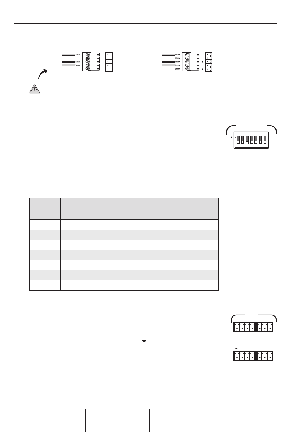
Step 7 (P/2 DA8 A and P/2 DA12 A models only)
Connect up to eight (P/2 DA8 A) or twelve (P/2 DA12 A) audio output devices to the 3.5 mm
5-pole captive screw connectors. Outputs can be balanced or unbalanced.
Unbalanced Stereo Output
Tip
NO GROUND HERE.
Sleeve(s)
Tip
NO GROUND HERE.
Balanced Stereo Output
Tip
Ring
Sleeve(s)
Tip
Ring
L
R
L
R
Left
Right
Left
Right
CAUTION
For unbalanced audio, connect the sleeve(s) to the center contact ground.
DO NOT
connect the sleeve(s) to the negative (-) contacts.
Configuration
Sync impedance DIP switches
Set the front panel DIP switches to correct for sync impedance mismatches,
or to solve laptop compatibility issues on the video input or reflection
problems on the video output.
Switch 1 (sync input impedance) —
The default setting is Off (510 ohms). If the image from
the laptop is unstable, slide DIP switch 1 to On (10k ohms).
Switches 2-7 (sync output impedance) —
Each of these switches controls a pair of outputs
simultaneously (see the table below). The default setting is Off (50 ohms). If the front LED is
green and all the input and output cables are connected correctly, but there is no image on the
display, slide the switch to On (75 ohms).
Switch
Function
Sync Impedance (ohms)
On
Off
1
Input sync
10,000
510
2
Output 1 and 2 sync
75
50
3
Output 3 and 4 sync
75
50
4
Output 5 and 6 sync
75
50
5
Output 7 and 8 sync
75
50
6
Output 9 and 10 sync
75
50
7
Output 11 and 12 sync
75
50
N
Switches 6 and 7 are available only on the P/2 DA12 series models.
Mute control
The mute control provides a way to mute individual outputs, or all outputs
at once. Audio and video for each output are muted simultaneously.
Each output is assigned to a pin on the captive screw connector. To mute
any output, short its pin to the ground pin ( ). Multiple outputs can be
shorted at the same time. To mute all outputs at once, short pin A (all) to the
ground pin.
The P/2 DA8 A model uses two 5-pole, 3.5 mm captive screw connectors.
The P/2 DA12 A model (shown at right) uses two 4-pole, 3.5 mm connectors and two 3-pole,
3.5 mm connectors.
If you have problems with the output from any of these distribution amplifiers, please consult
the Troubleshooting section of the full manual, which is available online at
.
If the pr
.
1 2 3 4 5
ON
ON
OFF
SYNC IMPEDANCE
6 7
1 2 3 4 5 6 7
2 4 6
8 10 12
1
A
3 5
7 9 11
MUTE